Engineering package
The drawings
Nineteen sheets of 1958 Alco Valve drawings, redrawn as clean vector schematics beside the sheets they come from. Every uncertain value is listed.
The May 1997 issue of Fulcrum reprinted 19 pages of the Alco Valve engineering package: freehand sketches, the pull-test graph, and the detail drawings for both test units. The sheets are photocopies of pencil and ink originals, most signed "Tilney" and marked "2X SIZE".
The four redraws below carry nothing that the sheets do not state. Interpolated, derived, or uncertain values are bracketed on the drawings and itemized in the list of uncertain values. The build specification is complete enough to repeat the 1958 test.
Test wiring
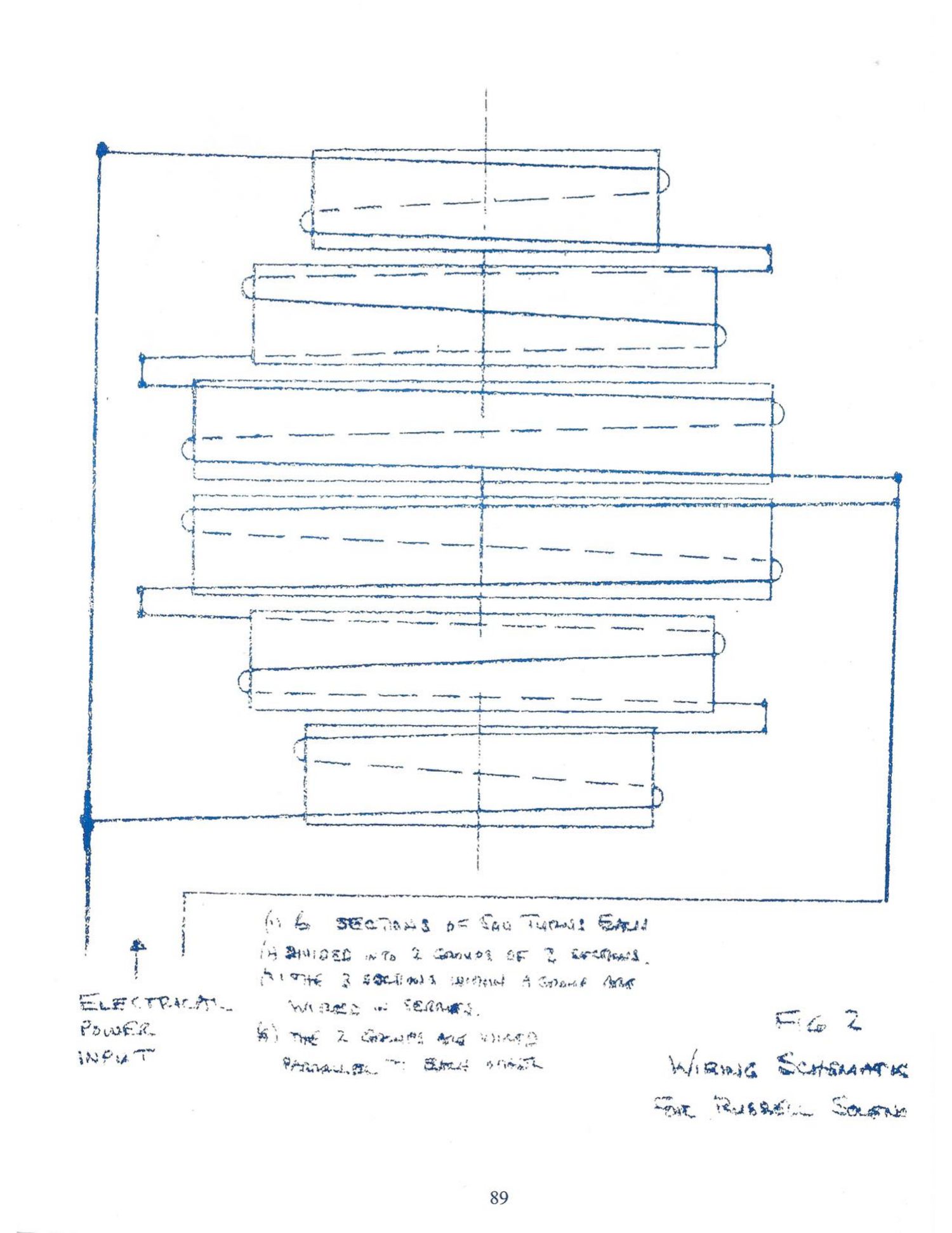
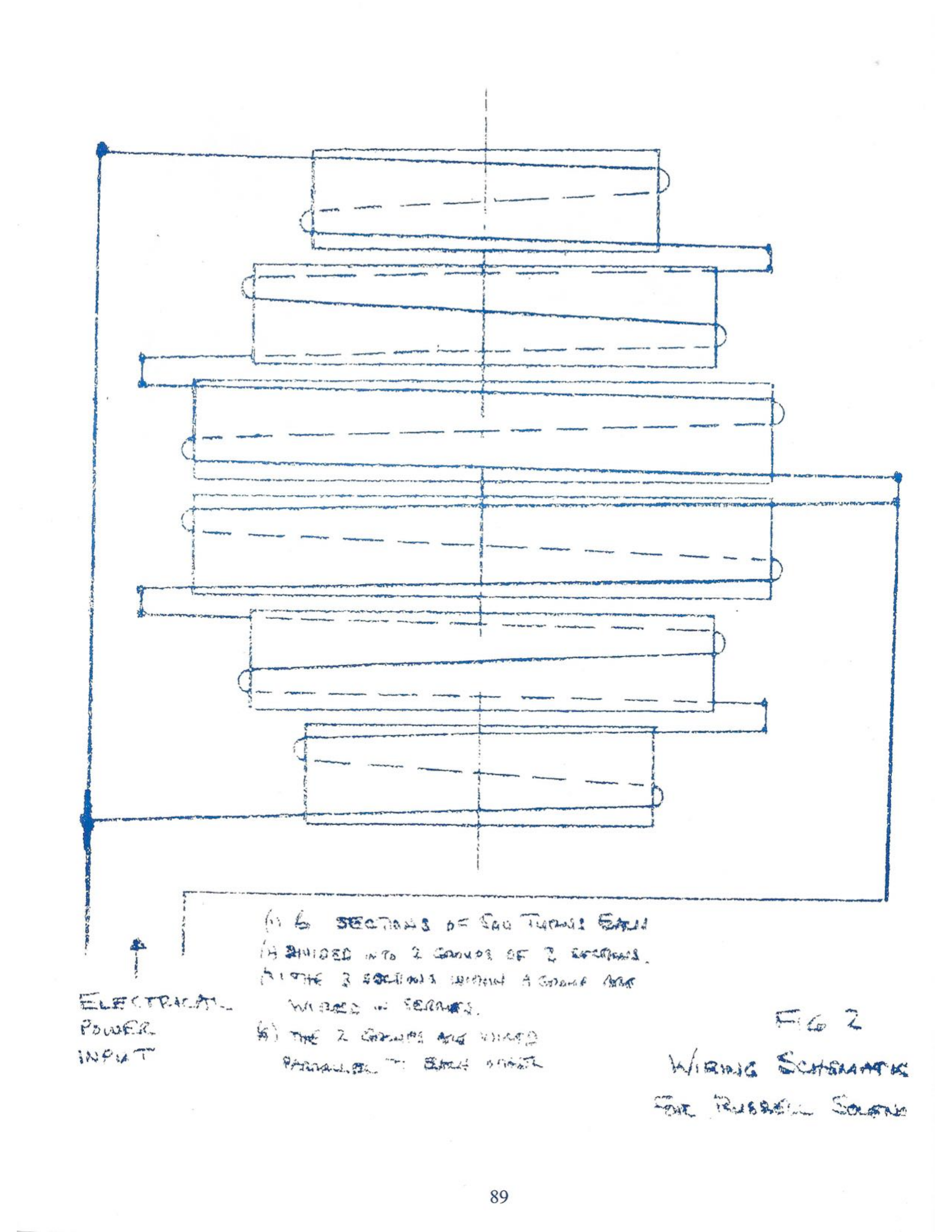
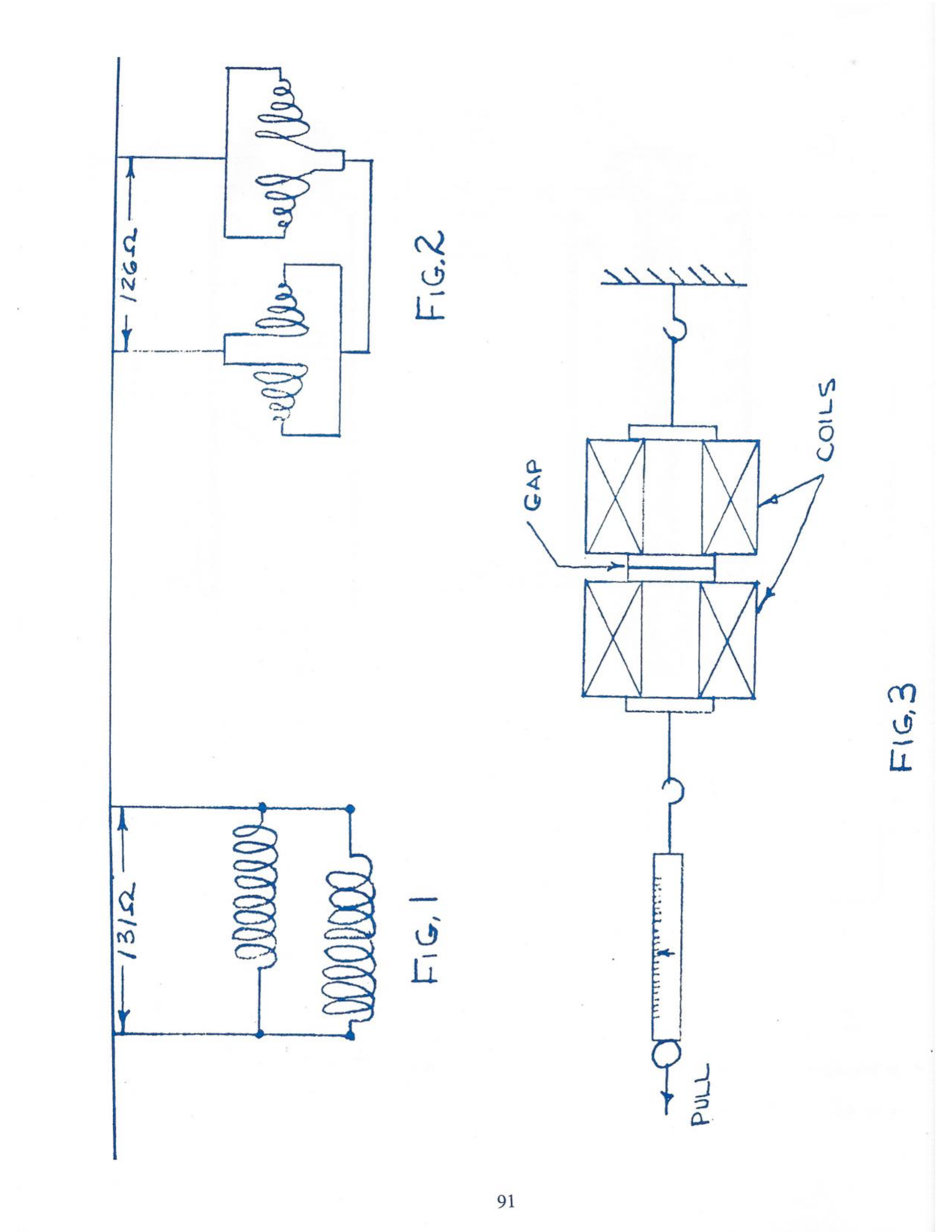
Six sections of 500 turns of #30 Bondeze wire. Two parallel groups of three sections in series. The measured set totals are 131 Ω for the conventional pair and 126 Ω for the Russell pair. The group composition is the natural reading of the source and is marked as an inference on the drawing.
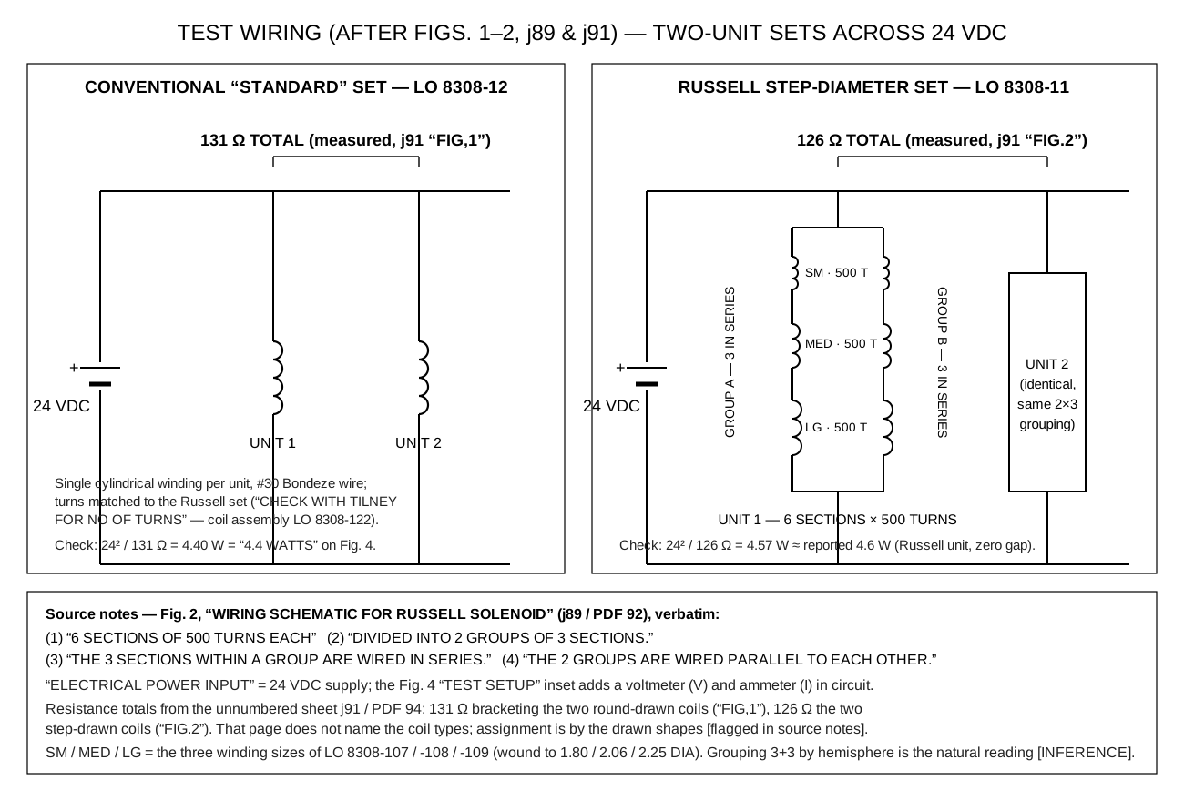
schematics/wiring_diagram.svg.
SVG source.
Coil cross-sections
Both units, drawn to the dimensions on the detail sheets. Bracketed values on the drawing are interpretive or derived: the .521 diameter feature, the core sleeve diameters, and the conventional wound diameter, which the source never dimensions.
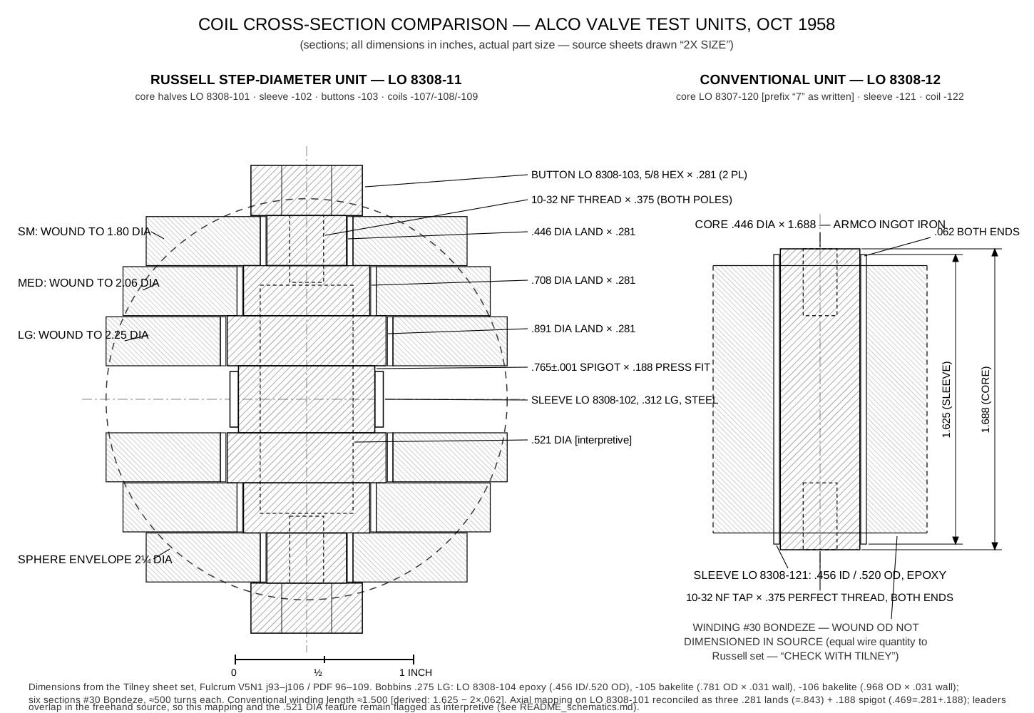
schematics/coil_comparison.svg.
SVG source.
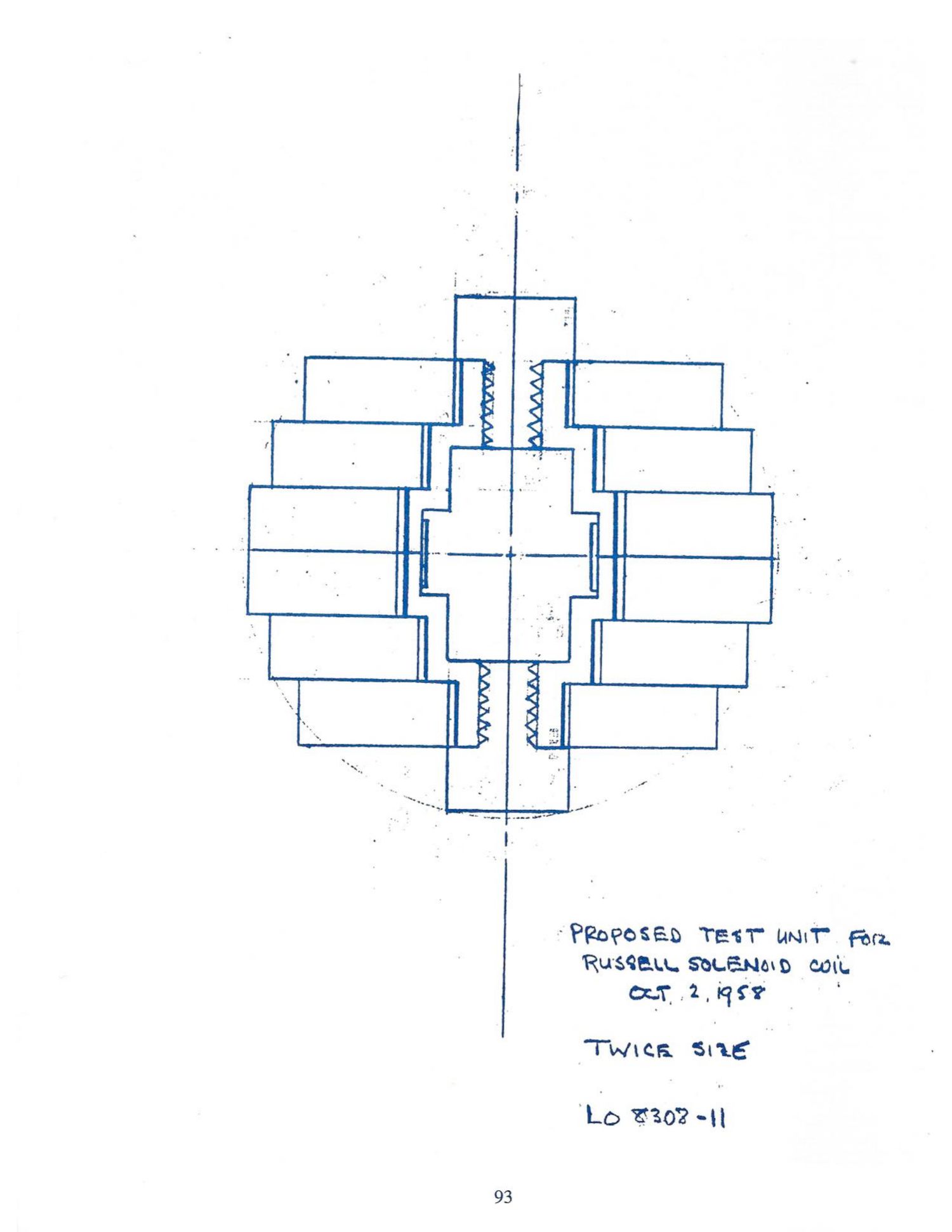
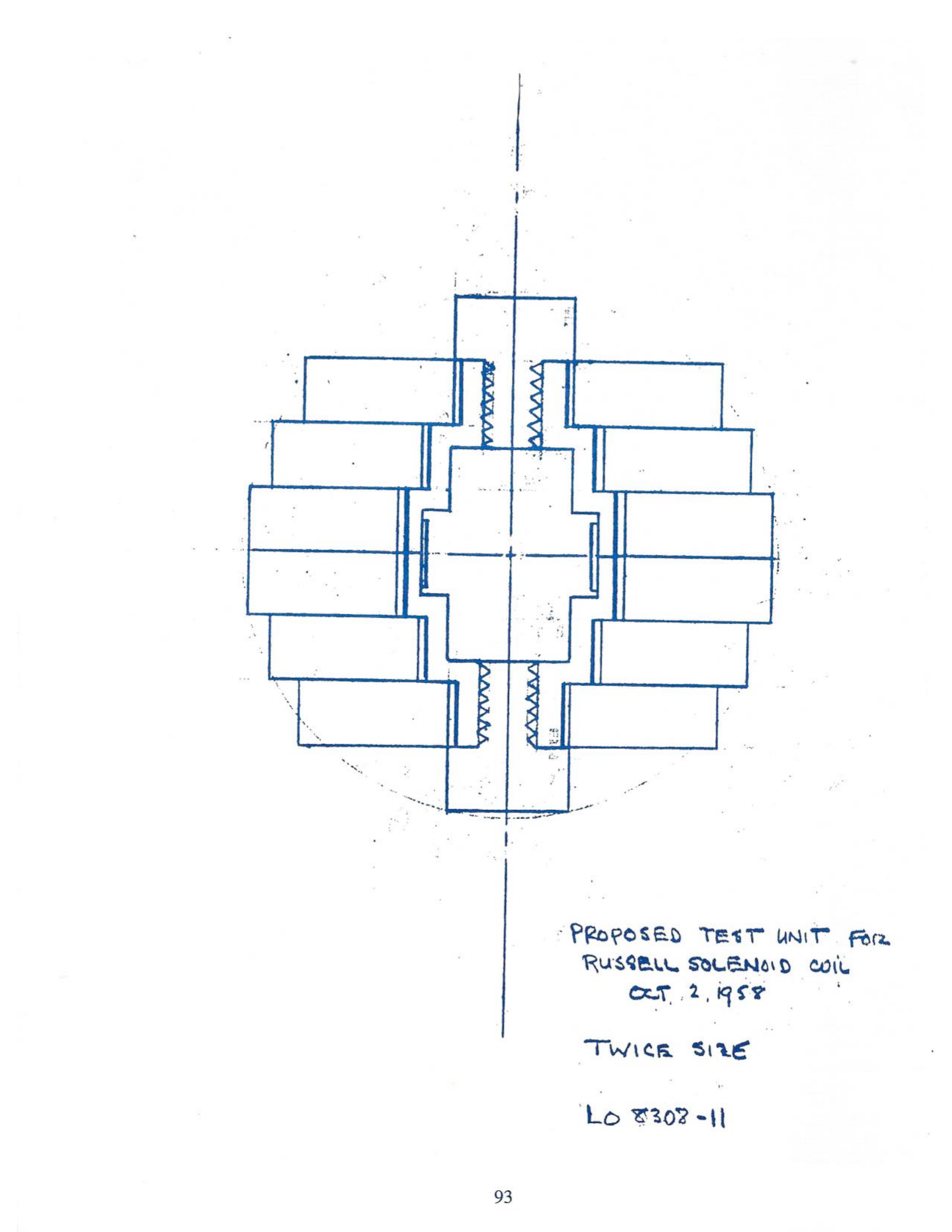
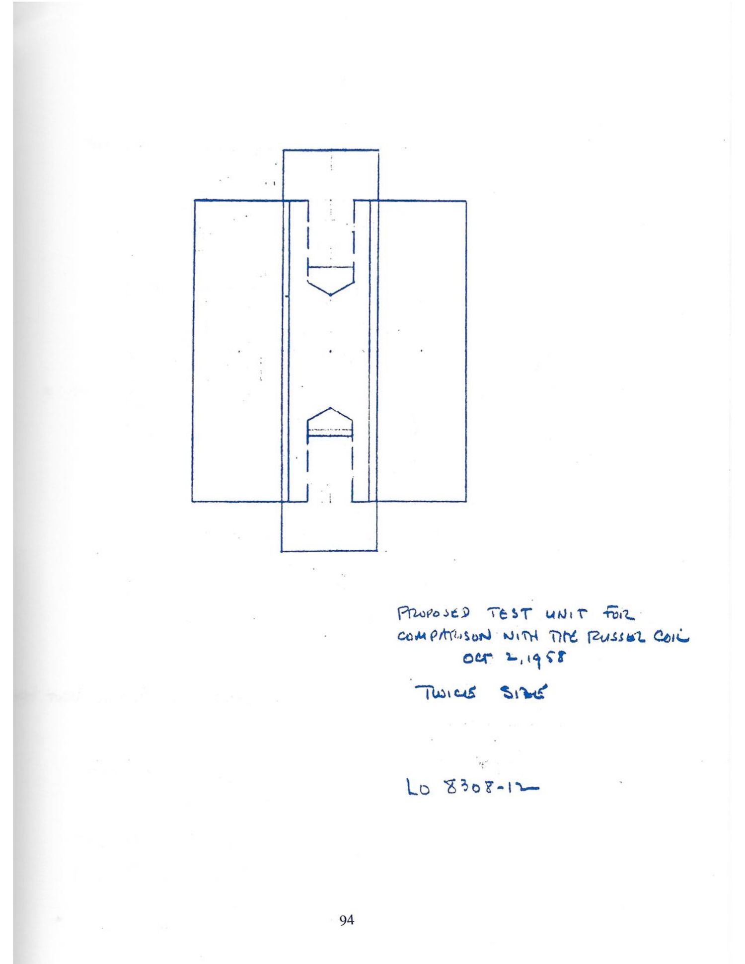
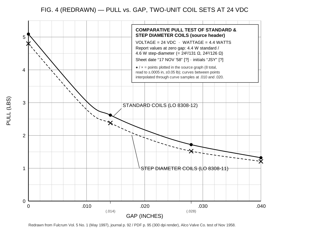
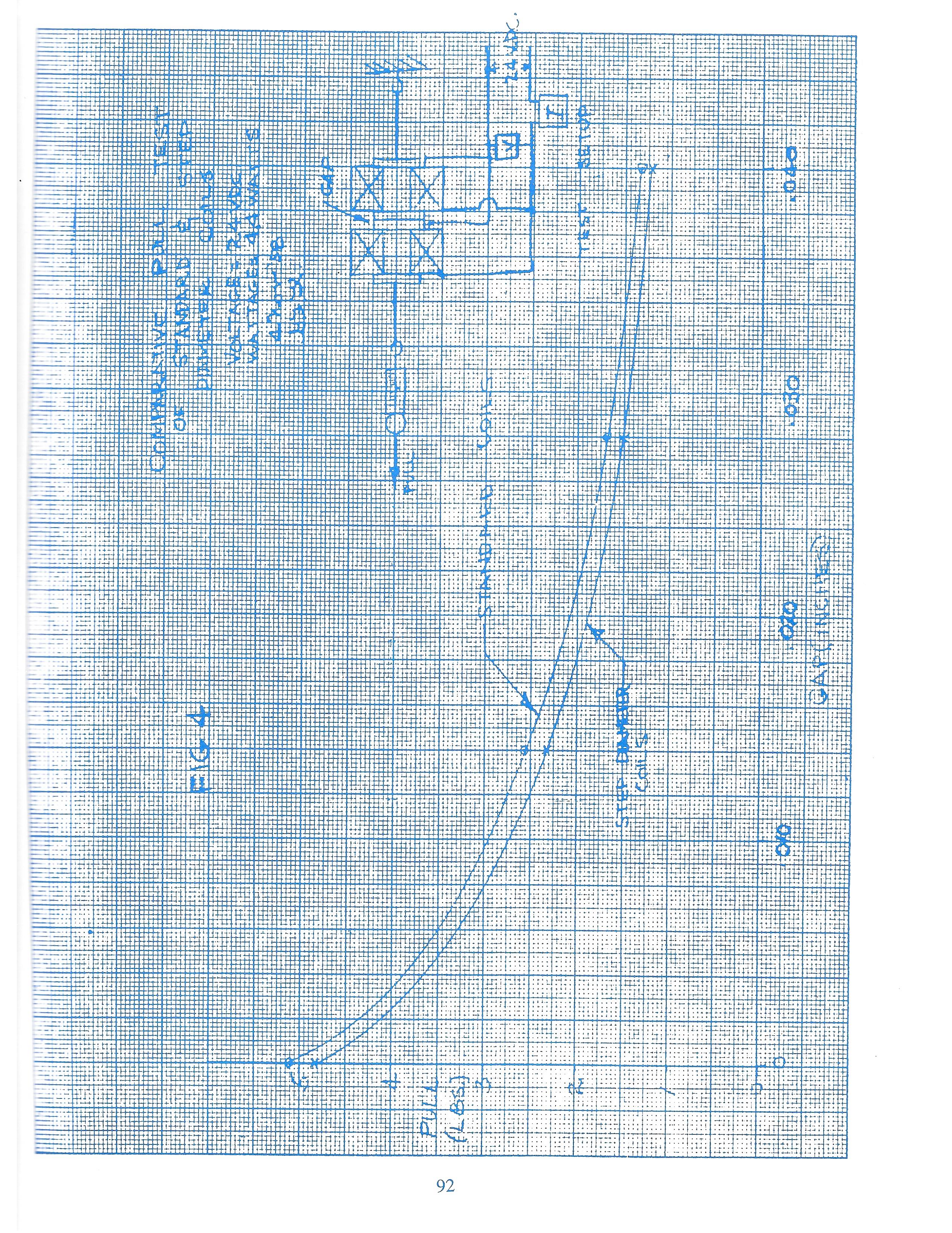
Fig. 4, the comparative pull test
Four plotted points per curve, at gaps of 0, .014, .028 and .040 in. Standard coils: 5.09, 2.62, 1.72 and 1.32 lb. Step-diameter coils: 4.80, 2.38, 1.52 and 1.21 lb.
schematics/pull_test_graph.svg.
SVG source.
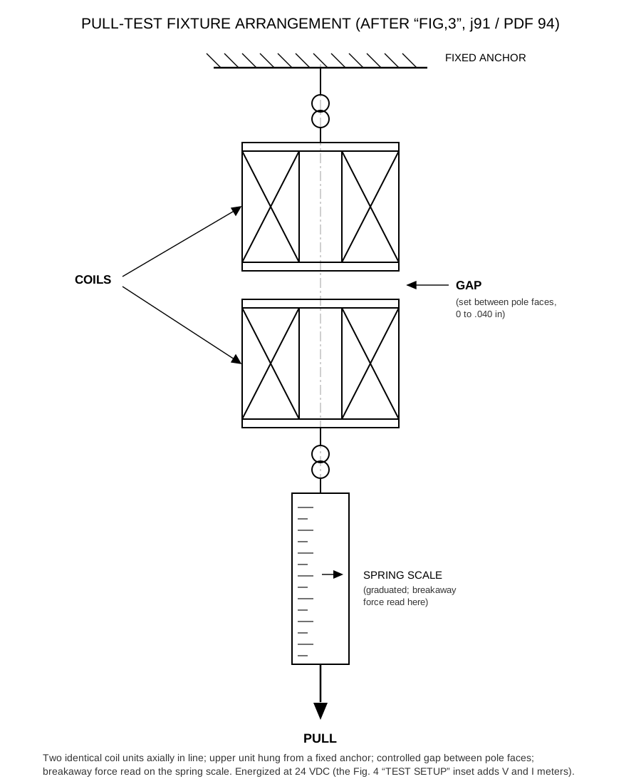
The pull-test fixture
Two coil units in line on one axis, with the gap between the buttons, a fixed anchor and a spring scale. The August 1958 bolt-through-core sketches, which the October 2 revision superseded, are not redrawn.
schematics/test_fixture.svg.
SVG source.
The nineteen reprinted sheets
All 19 pages at 300 dpi, in journal order. Click a sheet to enlarge it.
![Journal p. 104 / PDF p. 107: LO 8307-120 [8308-120?] — Core, conventional unit (.446 × 1.688)](scans/v5n1_300dpi_p-107.jpg)
How the redraws were made
This folder contains hand-written SVG redraws of the freehand engineering package printed in Fulcrum Vol. 5 No. 1 (May 1997), "From the Archives," journal pp. 88–106 (PDF pp. 91–109 of sources/fulcrum_v5n1_may_1997.pdf). The primary references are transcripts/v5n1_drawings_description.md and the 300 dpi renders sources/v5n1_renders/v5n1_300dpi_p-091.png … p-109.png. We re-verified all values against the 300 dpi renders before we drew the files. Nothing is invented. Uncertain or derived values are bracketed on the drawings themselves and itemized below.
File → source map
| File | Redraws | Source sheet(s) | Journal / PDF page |
|---|---|---|---|
wiring_diagram.svg | Test wiring: 6 sections × 500 turns #30 Bondeze, 2 parallel groups of 3 in series; conventional and Russell sets side by side with measured totals 131 Ω / 126 Ω across 24 VDC | Fig. 2 "Wiring Schematic for Russell Solenoid"; unnumbered resistance sheet ("FIG,1"/"FIG.2") | j89 / PDF 92; j91 / PDF 94 |
coil_comparison.svg | Cross-sections: Russell step-diameter unit (LO 8308-11) vs conventional unit (LO 8308-12); core geometry, winding envelopes, step profile, all stated dimensions | LO 8308-11, -12 (assembly concepts); details LO 8308-101, -102, -103, -104, -105, -106, -107, -108, -109; LO 8307-120, LO 8308-121, -122 | j93–j106 / PDF 96–109 |
pull_test_graph.svg | Fig. 4 comparative pull test: pull (lb) vs gap (in), both curves, test-condition caption box | Fig. 4 graph-paper sheet | j92 / PDF 95 |
test_fixture.svg | Pull-test fixture: two coil units axially in line, gap, fixed anchor, spring scale, PULL arrow | "FIG,3" on the resistance sheet | j91 / PDF 94 |
(We did not redraw the earlier Aug-1958 fixture sketches — Fig. 1 j88 and Fig. 3 j90, the bolt-through-core version that Dube's Oct 2 revision superseded. test_fixture.svg follows the as-tested arrangement of j91/j92.)
Fig. 4 data extraction (pull_test_graph.svg)
Method: we rotated the 300 dpi render (p-095) upright and calibrated it against the printed graph grid. We detected the major gridlines programmatically at 60.0 px per .001 in (x) and 61.4 px per 0.25 lb (y), anchored on the labeled axis values (0/.010/.020/.030/.040 in and 0–5 lb). We located the plotted marks by dark-pixel centroid in ±16 px windows.
Points read from the source (8 of 8 plotted points, read to ±.0005 in, ±0.05 lb):
| Gap (in) | Standard coils (●) | Step diameter coils (×) |
|---|---|---|
| .000 | 5.09 lb | 4.80 lb |
| .014 | 2.62 lb | 2.38 lb |
| .028 | 1.72 lb | 1.52 lb |
| .040 | 1.32 lb | 1.21 lb |
The source plots exactly these four points per curve — at gaps 0, ≈.0141, ≈.0280 and .040 in. The intermediate gaps measure 14.1 and 28.0 thousandths against the gridlines. The sheet does not state why those values were chosen.
Interpolated: the curve shape between marks. We read two shape samples per curve where each curve crosses the .010 and .020 gridlines (standard ≈3.0 / ≈2.2 lb, step ≈2.8 / ≈1.9 lb, ±0.1 lb — curve-line crossings, not plotted points). The drawn path is a smooth interpolation through the points + samples. Everything between those x-positions is interpolated, and this matches the source's hand-drawn dashed curves.
Correction vs. the first-pass transcript description: an earlier draft of v5n1_drawings_description.md gave the .040-in endpoints as ≈2.1 lb (standard) and ≈1.4 lb (step). Those values were read from a rough scan with a stated ±0.2 lb uncertainty. We re-read the 300 dpi render against the calibrated gridlines. This re-read puts the .040 endpoints at 1.32 lb and 1.21 lb. (The standard curve passes 2.1 lb near gap .020, which is the likely source of the misread.) The zero-gap values 5.09/4.80 vs the earlier ≈5.2/≈4.9 are within the stated tolerance. The corrected ratios (standard/step = 1.06, 1.10, 1.13, 1.09 at the four points) are consistent with the report's "5 to 10% more pulling power throughout the range" within reading uncertainty.
Cross-check: the graph header reads "VOLTAGE = 24 VDC, WATTAGE = 4.4 WATTS". The report wattages are 4.4 W (conventional) / 4.6 W (Russell). 24²/131 Ω = 4.40 W and 24²/126 Ω = 4.57 W. Thus the measured set resistances reproduce both reported wattages. This corroborates the 131/126 Ω readings. It also corroborates that the readings are the totals of each two-unit set as tested.
Values that are uncertain, interpolated, or derived
Every such value is bracketed on the drawings. The complete list is:
- Fig. 4 endpoints/date — curve values as above (±0.05 lb, ±.0005 in). The two zero-gap markers overlap the y-axis line and each other, so read them as ±0.1 lb. The sheet date "17 NOV '58" and the initials "JSY" are uncertain readings [transcript flag 3].
- 131 Ω / 126 Ω assignment — the j91 sheet does not name the coil types. The assignment (131 = round-drawn "FIG,1" = standard, 126 = step-drawn "FIG.2" = Russell) is by the drawn coil shapes [transcript flag 7]. The wattage cross-check above and the report's "Russell resistance 4% lower" corroborate it.
- Group composition — we read "2 groups of 3 sections" as one hemisphere per group (SM+MED+LG in series). This is the natural reading, and it is marked [INFERENCE] on
wiring_diagram.svg. - LO 8308-101 axial mapping — the freehand leaders overlap. The diameters (.446/.521/.708/.765±.001/.891) are secure. We mapped the axial figures (.188/.281/.281/.469/.843) as three winding lands of .281 each (sum .843, matching the two ".281" callouts and the ".843" chain) + a .188 spigot (.469 = .281 + .188 exactly). The mapping is internally consistent but still interpretive [transcript flag 2].
- ".521 DIA" feature — we drew it on
coil_comparison.svgas a dashed internal outline from the equatorial face, explicitly labeled [interpretive]. (In the 300 dpi render its solid outline begins where the tap-drill dashes end, which suggests an internal bore/relief.) It cannot be an external winding step (the three bobbin bores match .446/.708/.891). - Core sleeve LO 8308-102 ID/OD — the source gives ".688 DIA" (the leader suggests ID) and a ".767±.001" press-fit bore. The two cannot both be inside diameters, and the sheet does not resolve which is OD [transcript flag re: -102]. We drew the sleeve schematically (bore .767 over the .765 spigots, OD undimensioned). Only ".312 LG" appears as text.
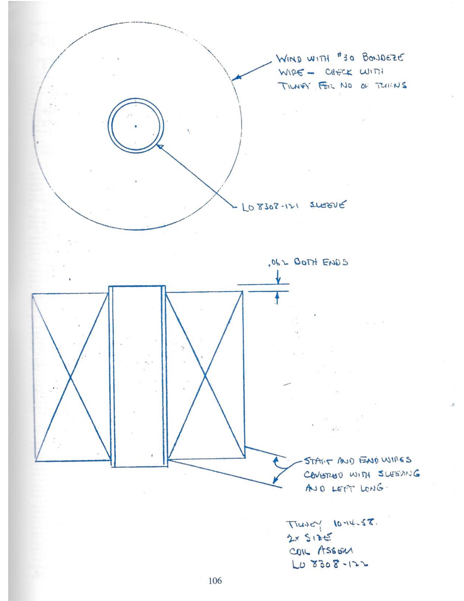
- Conventional wound OD — LO 8308-122 carries no wound-diameter dimension ("CHECK WITH TILNEY FOR NO OF TURNS"). We drew the winding outer edge dashed and labeled it "wound OD not dimensioned in source." Per Dube's letter, the wire quantity equals the Russell set.
- Conventional winding length ≈1.500 — derived: 1.625 sleeve − 2 × .062 end protrusion. The source does not dimension it.
- LO 8307-120 prefix — "8307" as written. It is probably a slip for 8308 [transcript flag 1].
- Turns per section ≈500 — nominal per Dube's Aug 25 letter and the Fig. 2 note. The assembly sheets say "record no. of turns", and the final counts are not stated anywhere.
- Sleeve-vs-spigot axial fit — the .312-long sleeve over two .188 spigots implies that the spigot faces butt at the equator, with ~.032 axial clearance to each .891 shoulder. The source does not make this explicit (we drew it accordingly and show no dimension).
Values not listed above (all diameters, land heights, lengths, thread callouts, materials, turn/group counts, resistances, voltages) come verbatim from the sheets.
Rendering
All four files are plain SVG 1.1, black-on-white, with viewBox set and no external resources. We validated them as well-formed XML and rendered them in Chromium at 800–1000 px wide for legibility.
Sheet-by-sheet description
The full description of all 19 sheets, dimension by dimension, from
transcripts/v5n1_drawings_description.md.
- Source issue: Fulcrum Vol. 5, No. 1, May 1997, "From the Archives," journal pp. 88–106 (PDF 91–109 of fulcrum_v5n1_may_1997.pdf)
- Renders: sources/v5n1_renders/ —
v5n1_p-0XX.png(150 dpi) andv5n1_300dpi_p-0XX.png(300 dpi) where XX = PDF page - All handwritten sheets are freehand pencil/ink drawings photocopied in blue. Most sheets show the signature "Tilney" (Alco draftsman) and the mark "2X SIZE" (drawn at twice scale — the stated dimensions are the actual part dimensions, and the one formal title block, LO 8308-104, confirms "SCALE 2:1")
- A [?] flag marks an uncertain reading. An [illegible] flag marks an illegible item
Conventions used below: dimensions are in inches, "j" = journal page, and "PDF" = page in fulcrum_v5n1_may_1997.pdf.
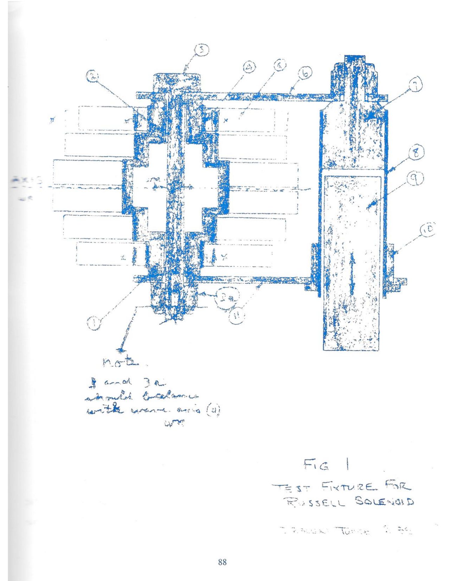
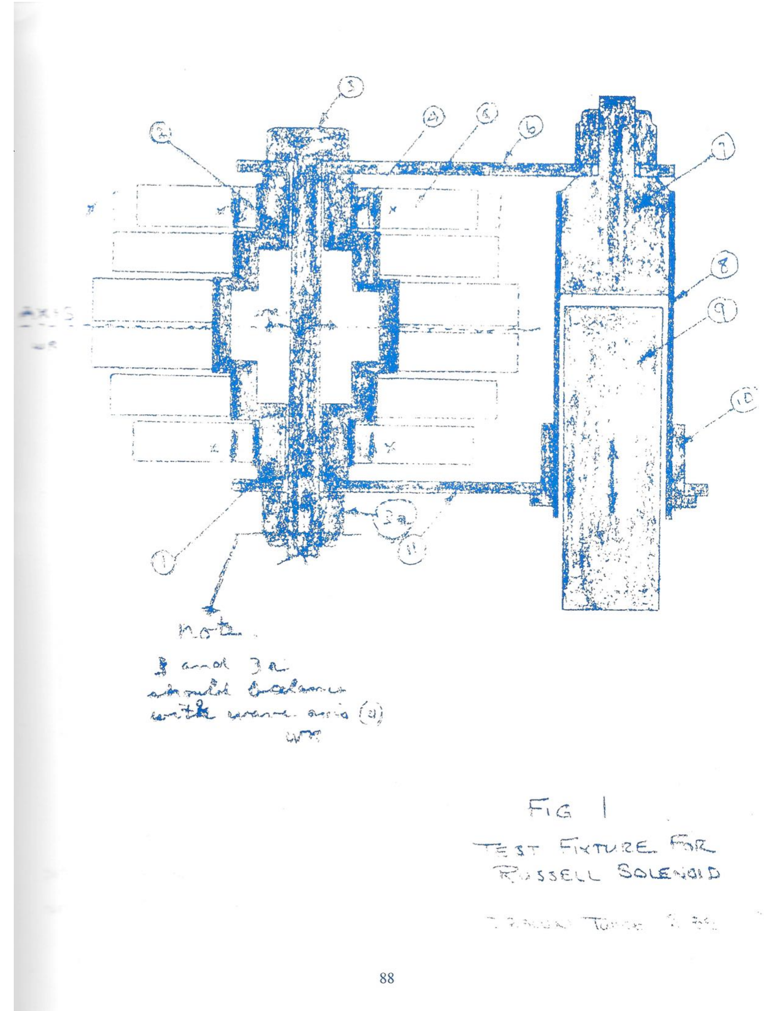
1. Fig. 1 — Test Fixture for Russell Solenoid (j88 / PDF 91)
This sheet is a freehand sectional sketch (blueprint copy, heavily reproduced) of the pull-test fixture per Dube's letter of Aug 25, 1958. The horizontal axis is labeled "AXIS". Balloon part numbers 1–11 identify the parts:
- (1), (2) identical stepped iron core halves (the "Russell core"), mirror-imaged about the center plane
- (3) axial bolt holding core halves and straps together (non-magnetic); a second balloon "3a" marks the bolt's far end/nut
- (4) insulating winding sleeves; (5) copper windings (drawn as stepped rectangular winding sections)
- (6), (11) flat iron straps top and bottom "conducting the energy" to the armature assembly
- (7) magnetic top plug; (8) non-magnetic enclosing tube; (9) magnetic armature (free to slide in tube); (10) magnetic bushing between tube and strap (11)
A handwritten cursive note (initialed, apparently by Walter Russell) reads: "note. 3 and 3a should balance with wave axis (4[?]) WR[?]" — the circled character after "wave axis" may be (a) or (4). [The word "balance" is fairly clear. The overall reading is uncertain.]
Caption: "FIG 1 / TEST FIXTURE FOR RUSSELL SOLENOID / [very faint line, possibly "DRAWN TILNEY 9-58" — mostly illegible]"
2. Fig. 2 — Wiring Schematic for Russell Solenoid (j89 / PDF 92)
This sheet is a freehand schematic. It shows six winding sections edge-on, stacked on a vertical axis. The section widths are stepped (narrow at top and bottom, widest pair at center) to suggest the sphere-approximating profile. Each section shows one representative turn (per Dube's letter, the actual count is ≈500 turns/section). An arrow labels the left-hand vertical bus "ELECTRICAL POWER INPUT". The right-hand bus is the return.
Handwritten notes (verified at 300 dpi):
- "6 SECTIONS OF 500 TURNS EACH"
- "DIVIDED INTO 2 GROUPS OF 3 SECTIONS."
- "THE 3 SECTIONS WITHIN A GROUP ARE WIRED IN SERIES."
- "THE 2 GROUPS ARE WIRED PARALLEL TO EACH OTHER." ["PARALLEL" and "OTHER" are partly smudged, but the reading is confident]
Caption: "FIG 2 / WIRING SCHEMATIC / FOR RUSSELL SOLEN[OID]" (edge cut off).
3. Fig. 3 — Test Fixture for Conventional Solenoid (j90 / PDF 93)
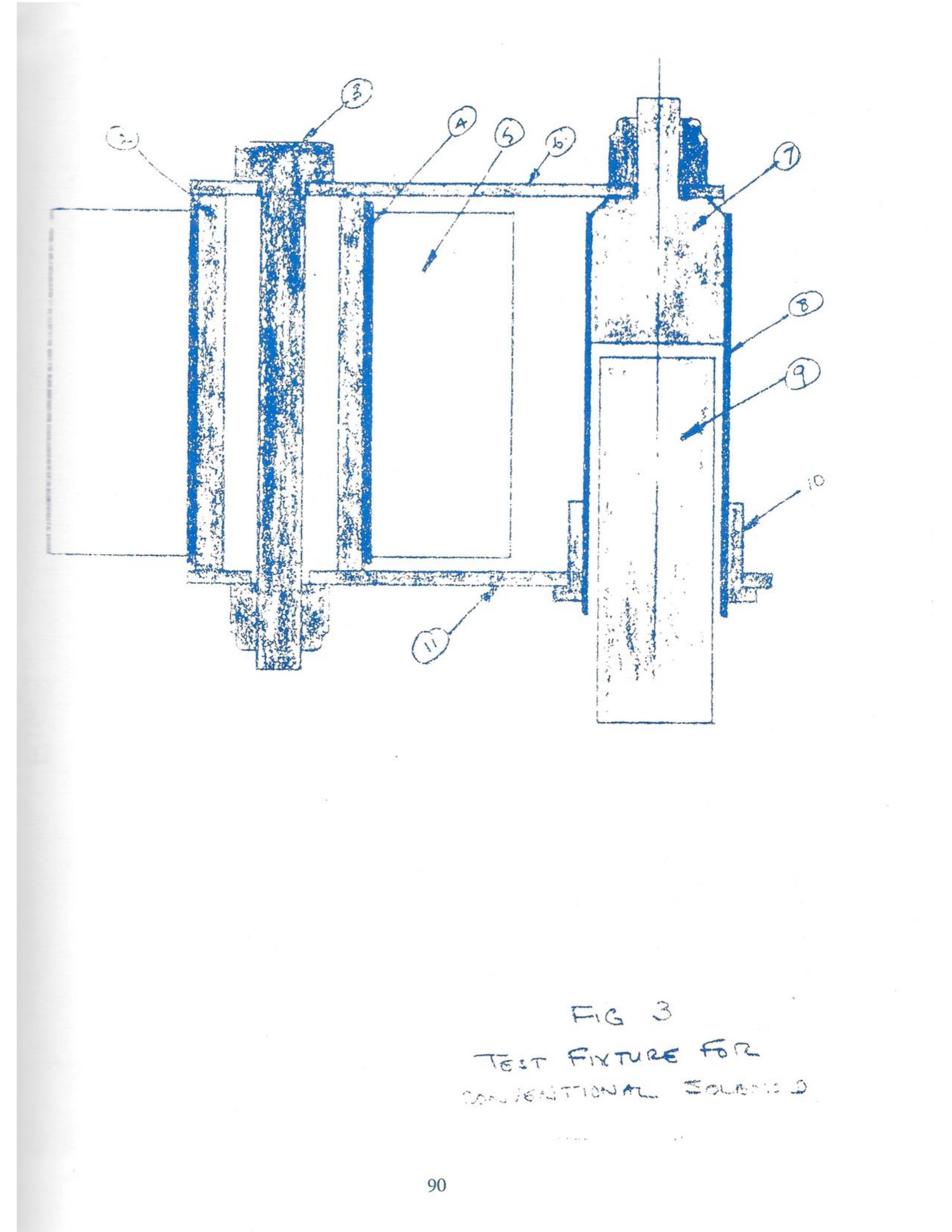
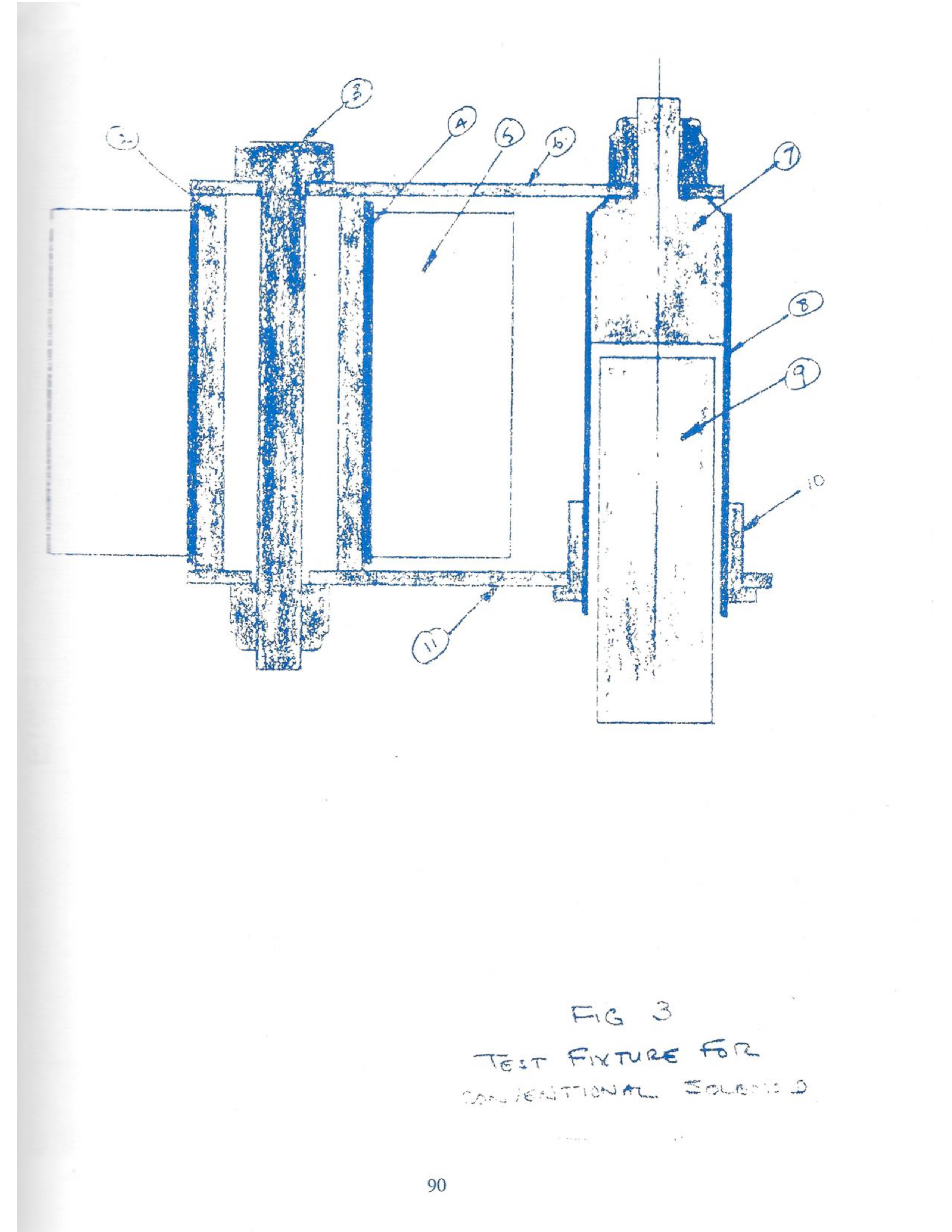
This sheet is a freehand sectional sketch with the same fixture architecture as Fig. 1. It shows a single cylindrical coil (4)/(5)/(6) on a straight iron core (3 = bolt, core drawn as a plain cylinder), with straps, top plug (7), enclosing tube (8), armature (9), bushing (10), and lower strap (11). Balloons 3, 4, 5, 6, 7, 8, 9, 10, and 11 are visible. Balloons 1/2 are not used — the straight core replaces the core halves.
Caption: "FIG 3 / TEST FIXTURE FOR / CONVENTIONAL SOLENOID [last word faint]".
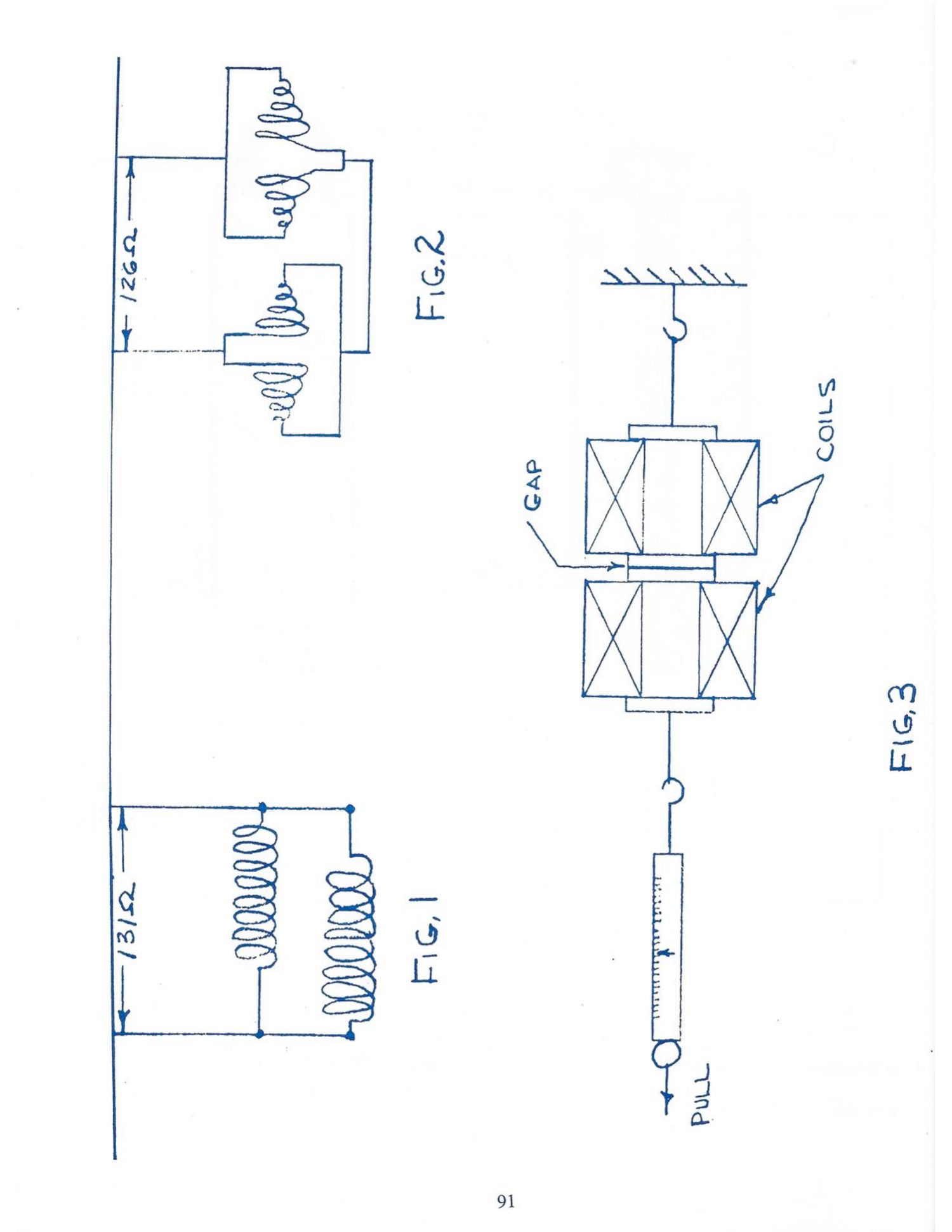
4. Figs. 1–3 (Russell-side sketch): coil resistances and pull-test rig (j91 / PDF 94)
This is a landscape freehand page with three small figures. Its "Fig" numbering is different from and later than items 1–3 above — evidently these are the test-report figures:
- "FIG, 1": two wound coils (drawn as helices) connected in parallel, bracketed with total "131 Ω"
- "FIG.2": two step-profile (conical/stepped) coils connected in parallel, bracketed with total "126 Ω"
- "FIG,3": pull-test arrangement — two coil stacks on a vertical axis separated by "GAP", with the label "COILS" and arrows to both stacks. The assembly hangs from a hatched ceiling anchor at top. Below are a spring scale (drawn with graduations) and an arrow labeled "PULL"
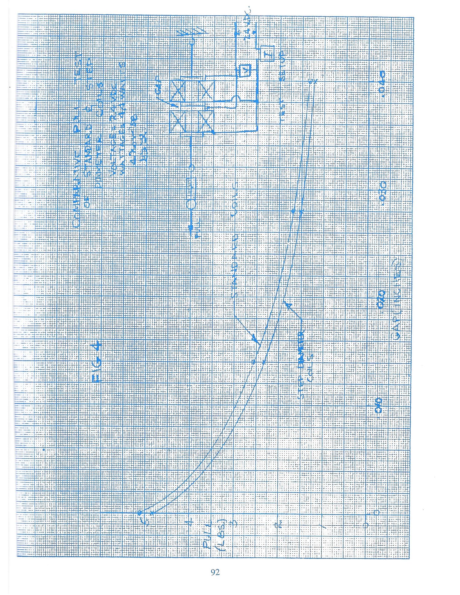
5. Fig. 4 — Comparative pull test graph (j92 / PDF 95)
This is a landscape sheet of fine graph paper. The header (verified at 300 dpi) reads: "COMPARATIVE PULL TEST OF STANDARD & STEP DIAMETER COILS / VOLTAGE = 24 VDC / WATTAGE = 4.4 WATTS / 17 NOV '58 [?] / JSY [initials, uncertain]"
An inset "TEST SETUP" schematic (upper right) shows two coil pairs with "GAP" between them, hung from a hatched anchor. A spring scale and a "PULL" arrow are at left. A circuit with voltmeter (V) and ammeter (I) symbols is fed from "24 VDC".
The vertical axis is "PULL (LBS)", 0–5, labeled at 1 lb (heavy paper gridlines every 0.5 lb). The horizontal axis is "GAP (INCHES)", 0–.040 (major gridlines at .010).
The sheet plots two curves. Both decrease monotonically, with 4 plotted points each at gaps 0/.014/.028/.040 in [calibrated re-read from the 300 dpi render, ±0.05 lb; the two zero-gap markers overlap the y-axis line and each other, so read them as ±0.1 lb. This re-read supersedes earlier approximate readings — see schematics/README_schematics.md]:
- "STANDARD COILS" (upper curve): 5.09 / 2.62 / 1.72 / 1.32 lb
- "STEP DIAMETER COILS" (lower curve): 4.80 / 2.38 / 1.52 / 1.21 lb
The standard (conventional) coils out-pull the step-diameter (Russell) coils at every gap. This is the measured verdict against Russell's predicted 40–60% advantage.
6. LO 8308-11 — Proposed Test Unit for Russell Solenoid Coil (j93 / PDF 96)
Caption: "PROPOSED TEST UNIT FOR / RUSSELL SOLENOID COIL / OCT. 2, 1958 / TWICE SIZE / LO 8308-11"
This sheet is a freehand sectional elevation on a vertical axis. It shows the sphere-approximating stepped assembly. Six winding blocks (three sizes, mirrored about the horizontal center plane) surround a central stepped core. The core halves meet at the equator (no through hole). Threaded studs/tapped bosses emerge on the axis at top and bottom (thread engagement drawn as zig-zag). A faint construction circle circumscribes the stepped profile and shows the intended spherical envelope. This sheet has no dimensions — it is the assembly concept. The detail parts are LO 8308-101 through -109 below.
7. LO 8308-12 — Proposed Test Unit for comparison with the Russell Coil (j94 / PDF 97)
Caption: "PROPOSED TEST UNIT FOR / COMPARISON WITH THE RUSSEL [sic] COIL / OCT 2, 1958 / TWICE SIZE / LO 8308-12"
This sheet is a freehand sectional elevation. It shows a single rectangular winding block (wide horizontal rectangle) on a straight cylindrical core. The core pieces enter from top and bottom inside a thin sleeve. They terminate in chamfered/pointed ends that face each other near the center (small gap between points — drawn as opposing arrow-head profiles). The vertical tube extends beyond the winding top and bottom. The sheet has no dimensions. The detail parts are LO 8307-120, LO 8308-121, and LO 8308-122 below.
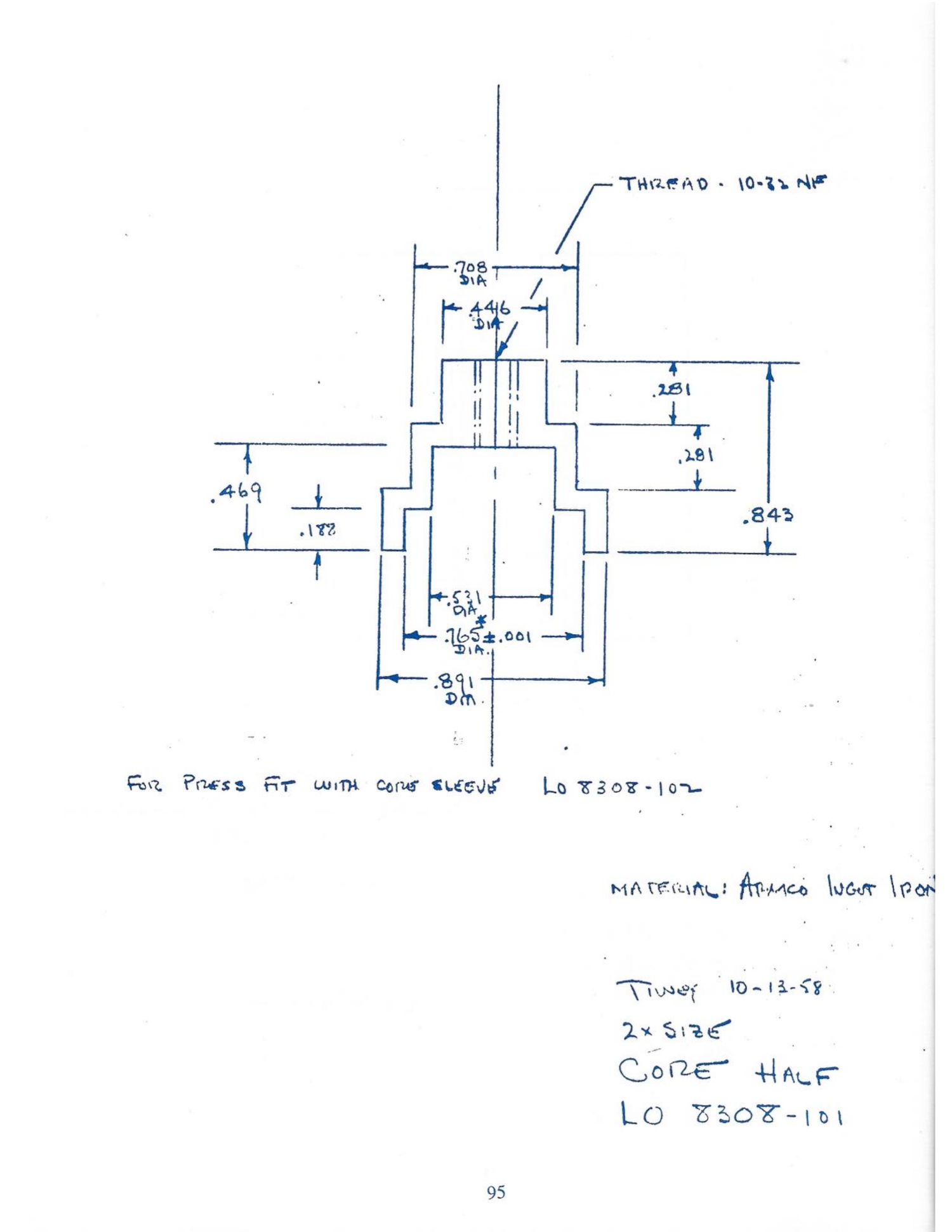
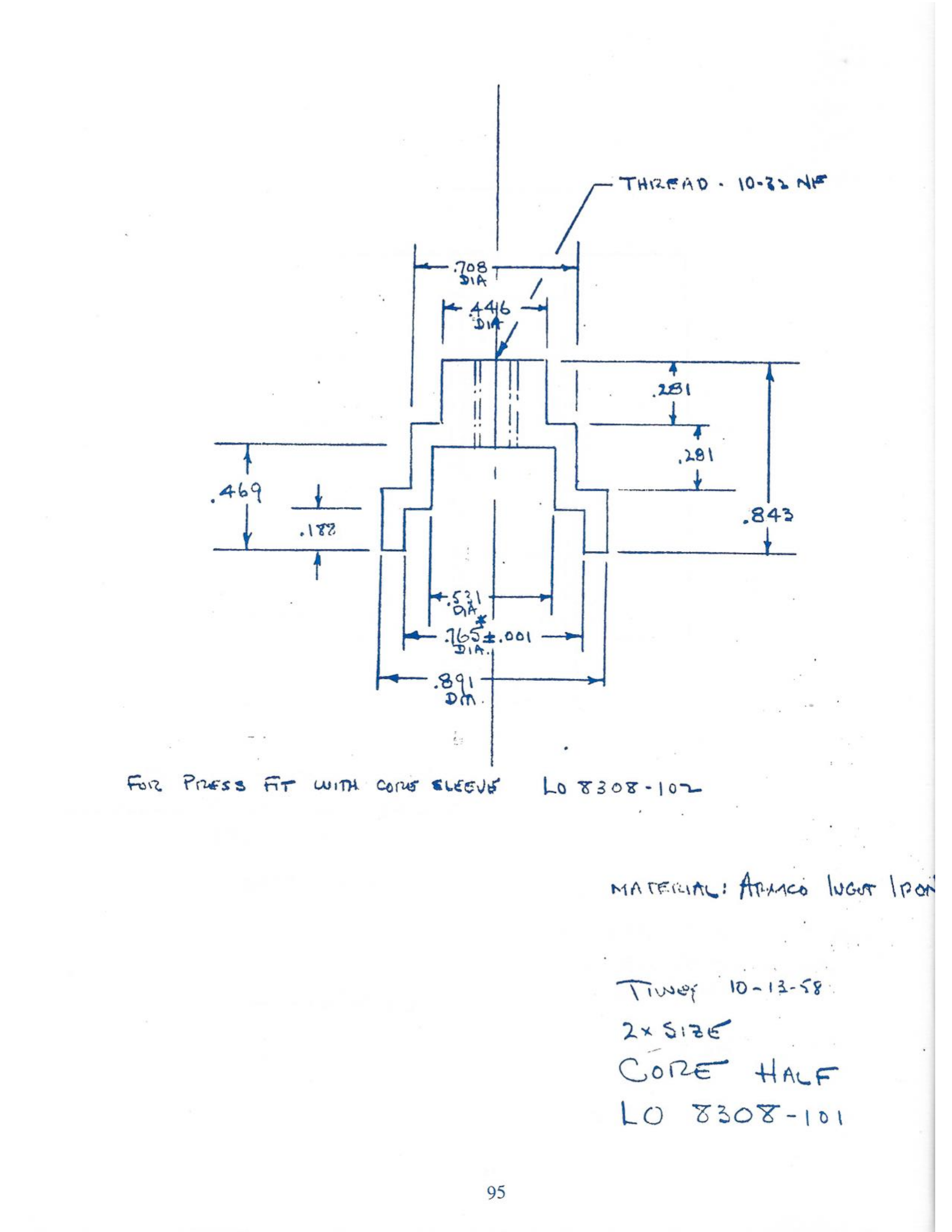
8. LO 8308-101 — Core Half (j95 / PDF 98)
Caption block: "TILNEY 10-13-58 / 2X SIZE / CORE HALF / LO 8308-101"; "MATERIAL: ARMCO INGOT IRON"
This sheet is a dimensioned freehand detail of the stepped core half. The part is a body of revolution, tapped axially, with three diameters that step down toward the outer end:
- Axial tapped hole at outer end: "THREAD · 10-32 NF"
- Outer step: .708 DIA; hole boss: .446 DIA
- Step heights (from outer end): .281, then .281 (two equal steps); overall height of the two stepped lands: .843
- Left side: .469 (height of largest-diameter land region) and .188 (step)
- Mid diameter: .521 DIA
- Spigot: .765 ±.001 DIA, marked "*" — "FOR PRESS FIT WITH CORE SLEEVE LO 8308-102"
- Largest diameter: .891 DIA
[The dimension-to-feature mapping is partly interpretive because the freehand leaders overlap. The five diameters read .446 / .521 / .708 / .765±.001 / .891. The axial figures read .188 / .281 / .281 / .469 / .843.]
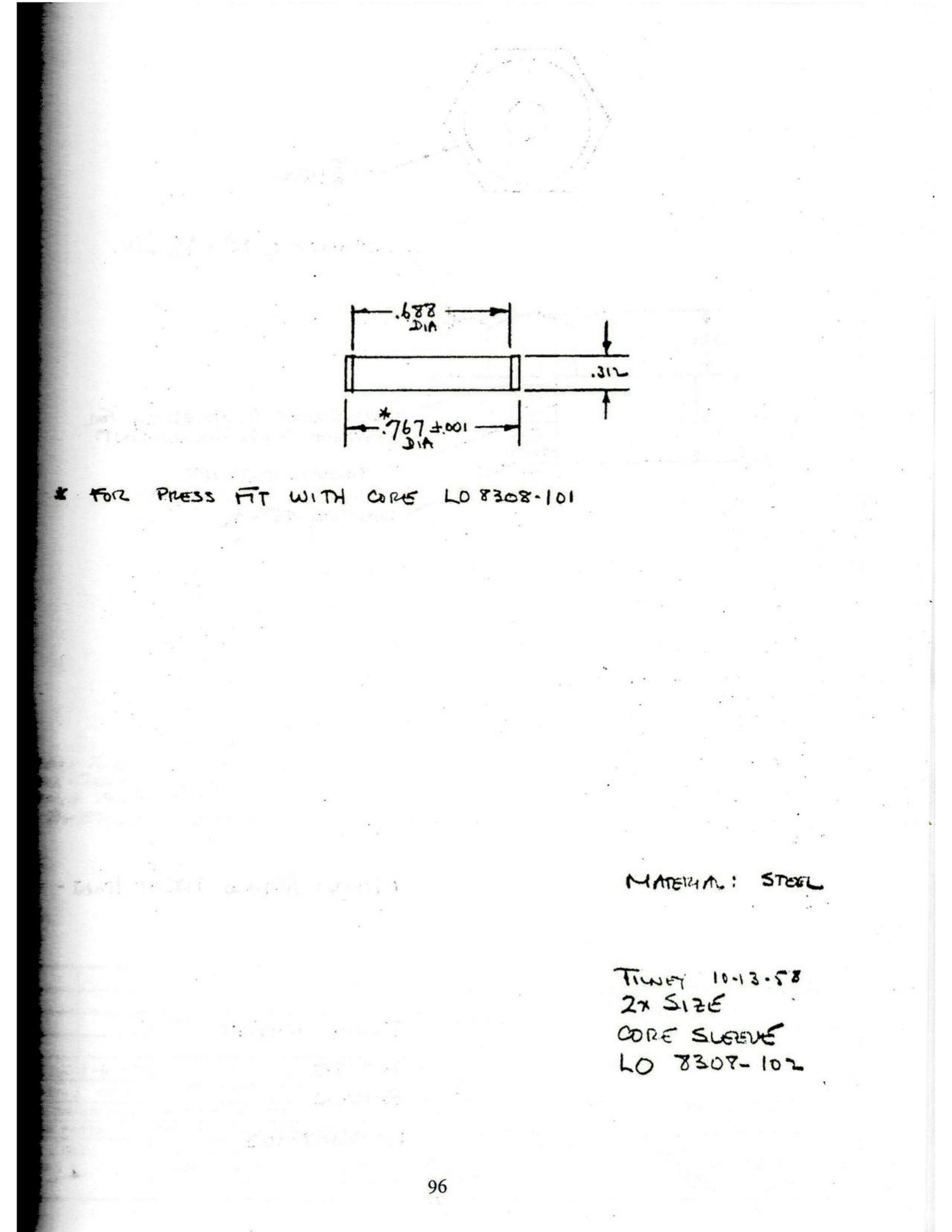
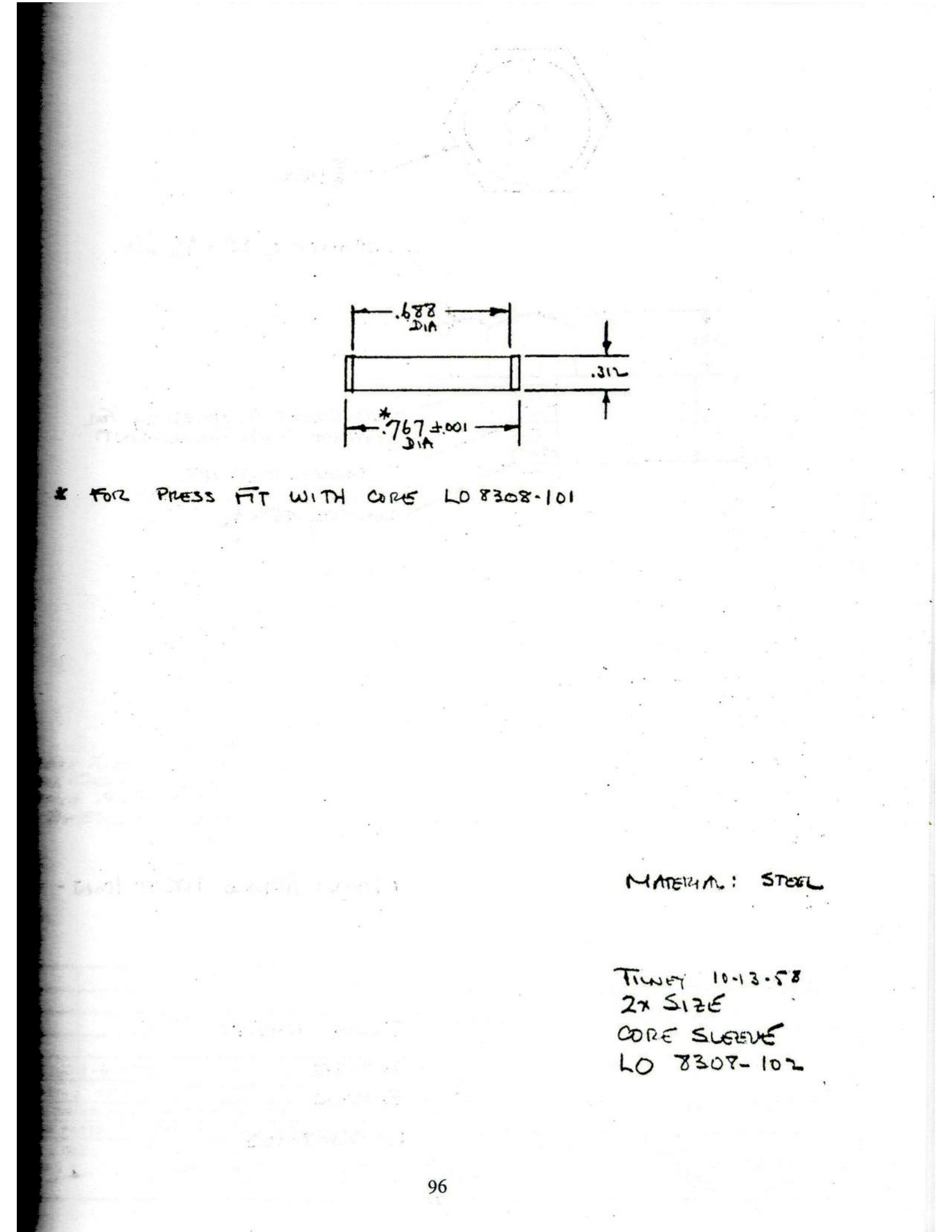
9. LO 8308-102 — Core Sleeve (j96 / PDF 99)
Caption block: "TILNEY 10-13-58 / 2X SIZE / CORE SLEEVE / LO 8308-102"; "MATERIAL: STEEL"
The part is a simple ring/sleeve. The dimensions are:
- .688 DIA (inner) [leader placement suggests ID]
- .767 ±.001 DIA, marked "" — " FOR PRESS FIT WITH CORE LO 8308-101"
- .312 (axial length)
A faint hex outline ghost appears at top of page (show-through or erased sketch of the button head, LO 8308-103).
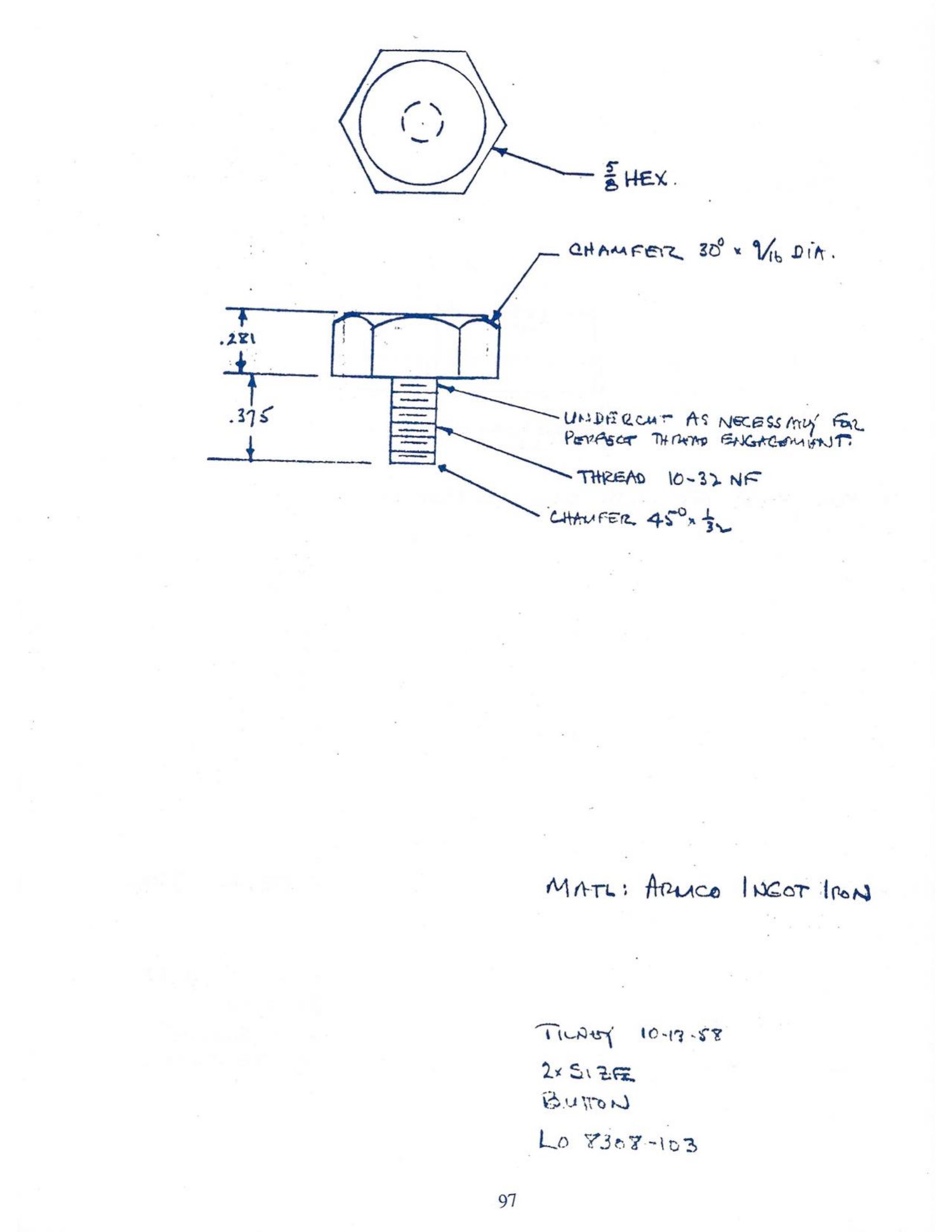
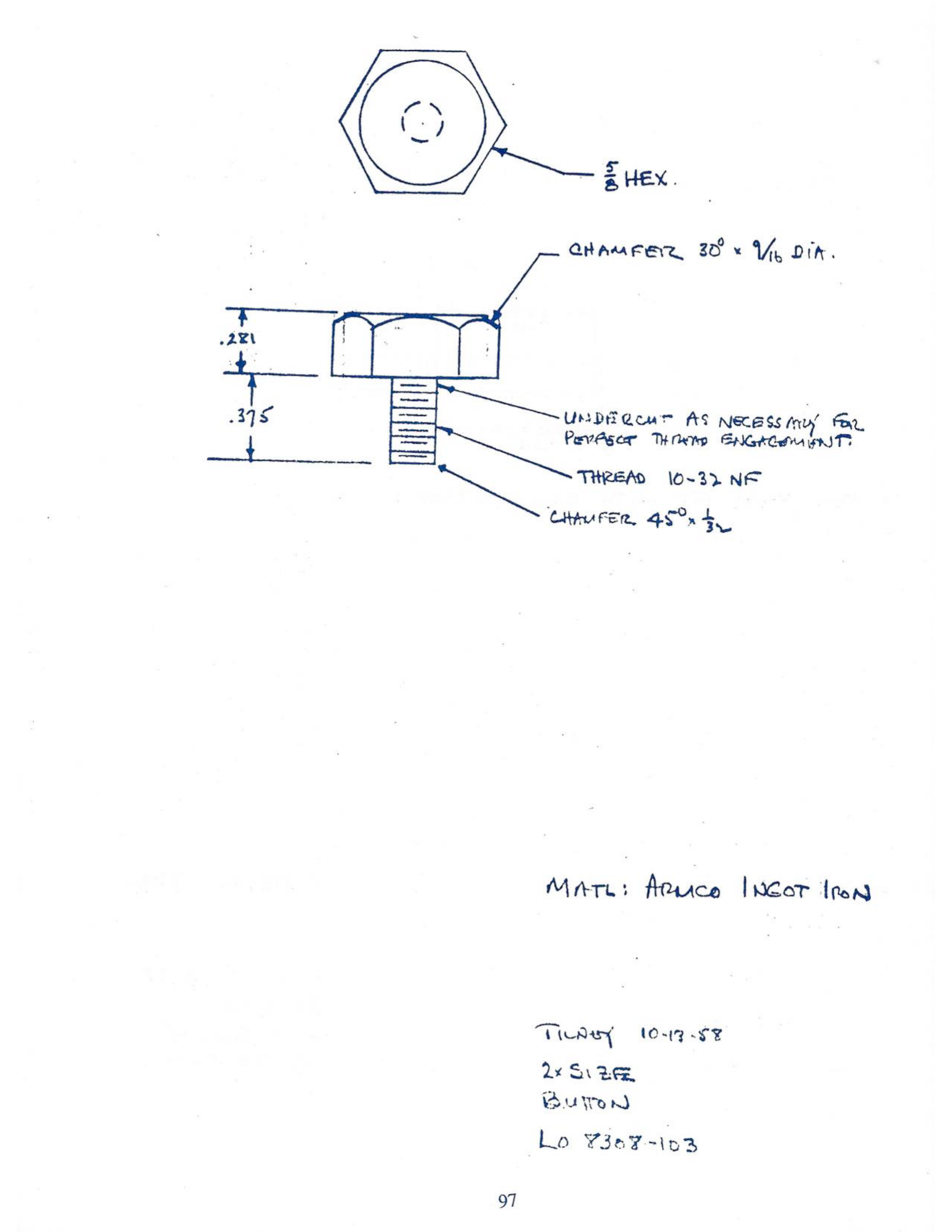
10. LO 8308-103 — Button (j97 / PDF 100)
Caption block: "TILNEY 10-13-58 / 2X SIZE / BUTTON / LO 8308-103"; "MATL: ARMCO INGOT IRON"
The part is a hex-headed threaded stud. It screws into the tapped end of each core half:
- Head: "5/8 HEX."; "CHAMFER 30° × 9/16 DIA."
- Head height: .281
- Thread length: .375; "THREAD 10-32 NF"
- "UNDERCUT AS NECESSARY FOR PERFECT THREAD ENGAGEMENT."
- "CHAMFER 45° × 1/32" (thread end)
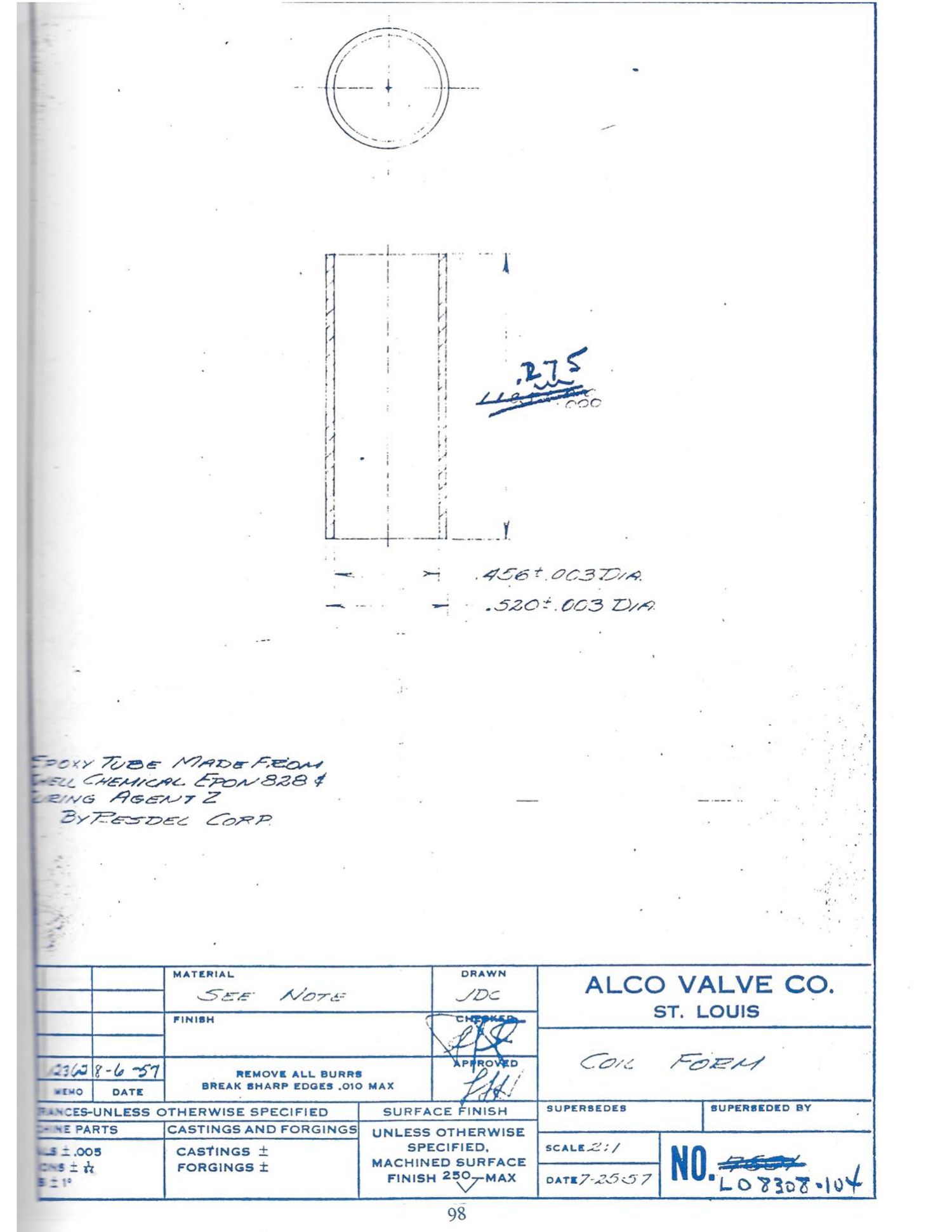
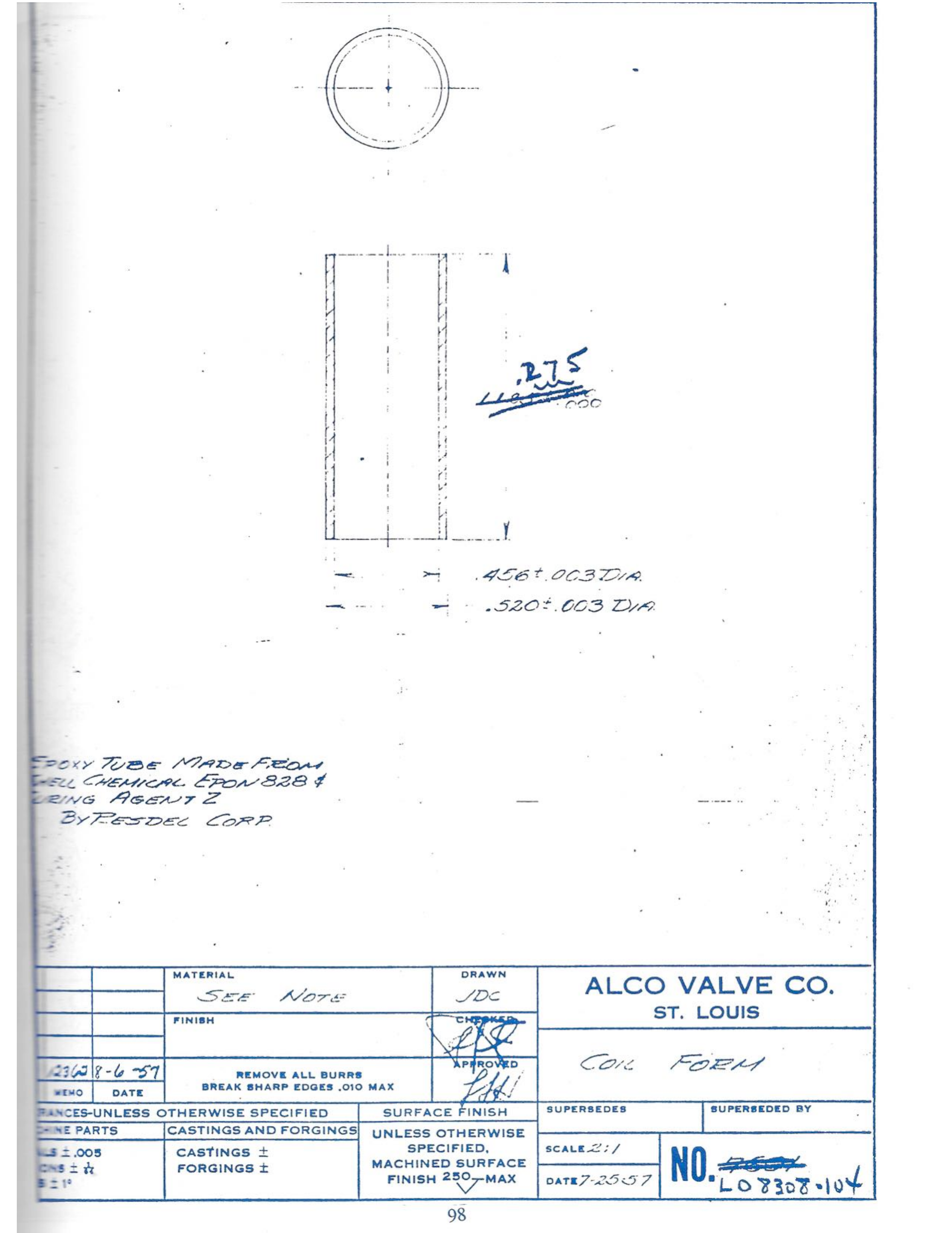
11. LO 8308-104 — Coil Form, small (j98 / PDF 101)
This is a formal Alco Valve Co. bordered drawing — the only sheet in the set with a full title block:
- Title block: "ALCO VALVE CO. / ST. LOUIS — COIL FORM"; DRAWN "JDC"; SCALE "2:1"; DATE "7-25-57"; NO. (crossed out: "7654" [?]) → handwritten "LO 8308-104"; MATERIAL "SEE NOTE"; memo "12362 [?] 8-6-57"; "REMOVE ALL BURRS / BREAK SHARP EDGES .010 MAX"; standard tolerance block ("...UNLESS OTHERWISE SPECIFIED", "±.005" etc., partly cut off at left edge)
- Note (handwritten): "EPOXY TUBE MADE FROM SHELL CHEMICAL EPON 828 & CURING AGENT Z / BY RESDEL CORP." [first characters of each line cut off by page edge; "RESDEL" reading fair]
- Tube, section hatched: ".456 ±.003 DIA" (ID) and ".520 ±.003 DIA" (OD)
- Length: original dimension crossed out (illegible, "±.000" visible) and replaced in handwriting: ".275"
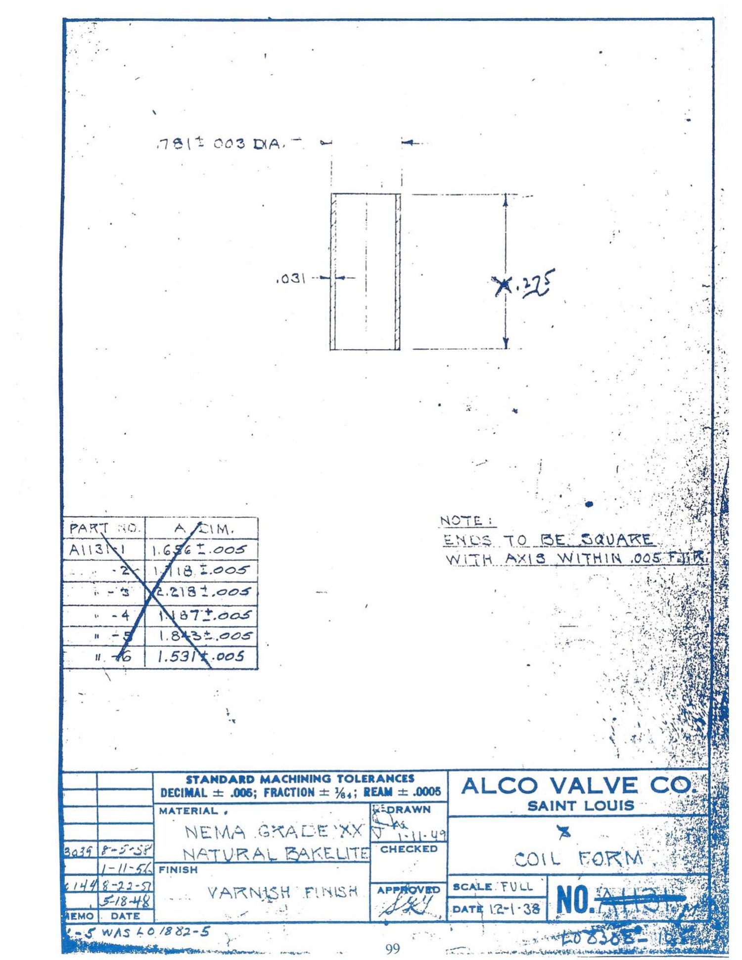
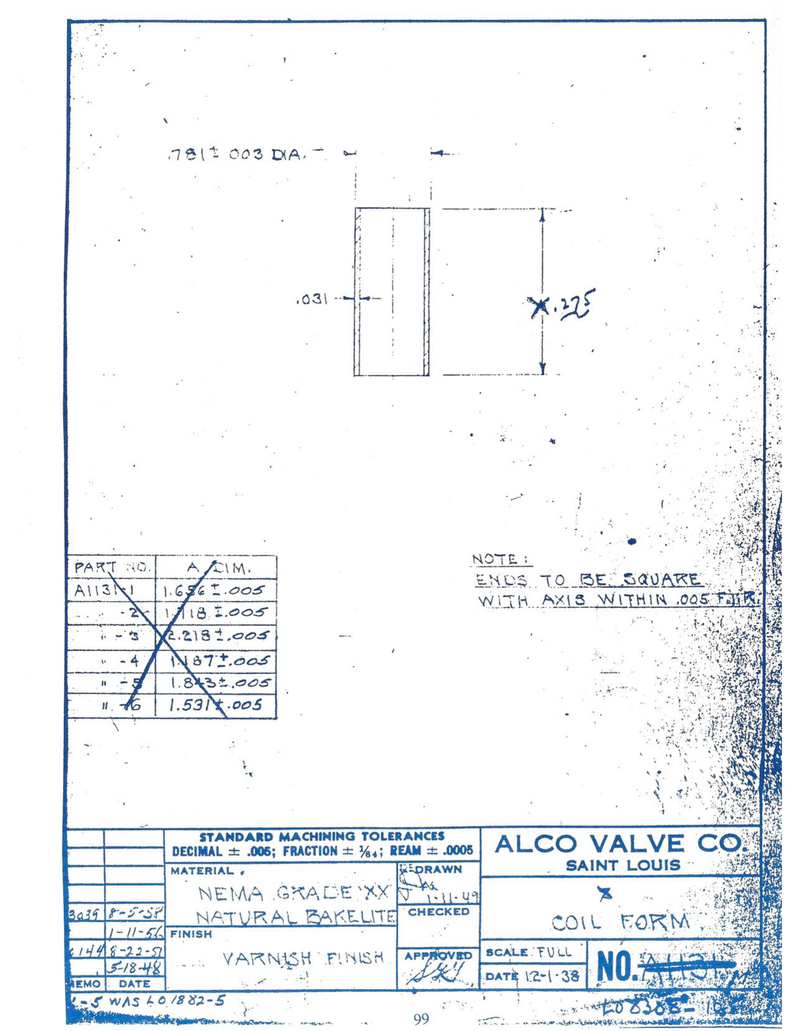
12. LO 8308-105 — Coil Form, medium (j99 / PDF 102)
This sheet is a reused old Alco bordered drawing (very dirty copy):
- Title block: "ALCO VALVE CO. / SAINT LOUIS — COIL FORM"; MATERIAL "NEMA GRADE XX NATURAL BAKELITE"; FINISH "VARNISH FINISH"; REDRAWN "1-11-49"; SCALE FULL; DATE "12-1-38"; NO. "A1131" crossed out → handwritten "LO 8308-105" [trailing digit partly cut off]; memo entries "13039 8-5-58" [?], "1-11-56", "2144 8-22-51" [?], "5-18-48"; bottom margin: "-5 WAS LO 1882-5"
- Part table (all rows crossed out): PART NO. A1131-1…-6 with "A" DIM. 1.656, 1.118, 2.218, 1.187, 1.843, 1.531 (all ±.005)
- Tube, section: ".781 ±.003 DIA." (OD); wall ".031"; length: table dimension replaced by handwritten "✗ .275"
- "NOTE: ENDS TO BE SQUARE WITH AXIS WITHIN .005 F.I.R."
13. LO 8308-106 — Coil Form, large (j100 / PDF 103)
This sheet is a reused old Alco bordered drawing:
- Title block: "ALCO VALVE CO. / ST. LOUIS"; title "1¼″ COIL FORM" (crossed out); MATERIAL "NEMA GRADE XX NATURAL BAKELITE"; FINISH "VARNISH FINISH"; REDRAWN "H E S 5-7-56"; CHECKED "MOHOW"; SCALE FULL; DATE "7-6-38"; memo "6-2-48"; NO. "A1054-D" crossed out → handwritten "LO 8308-106"
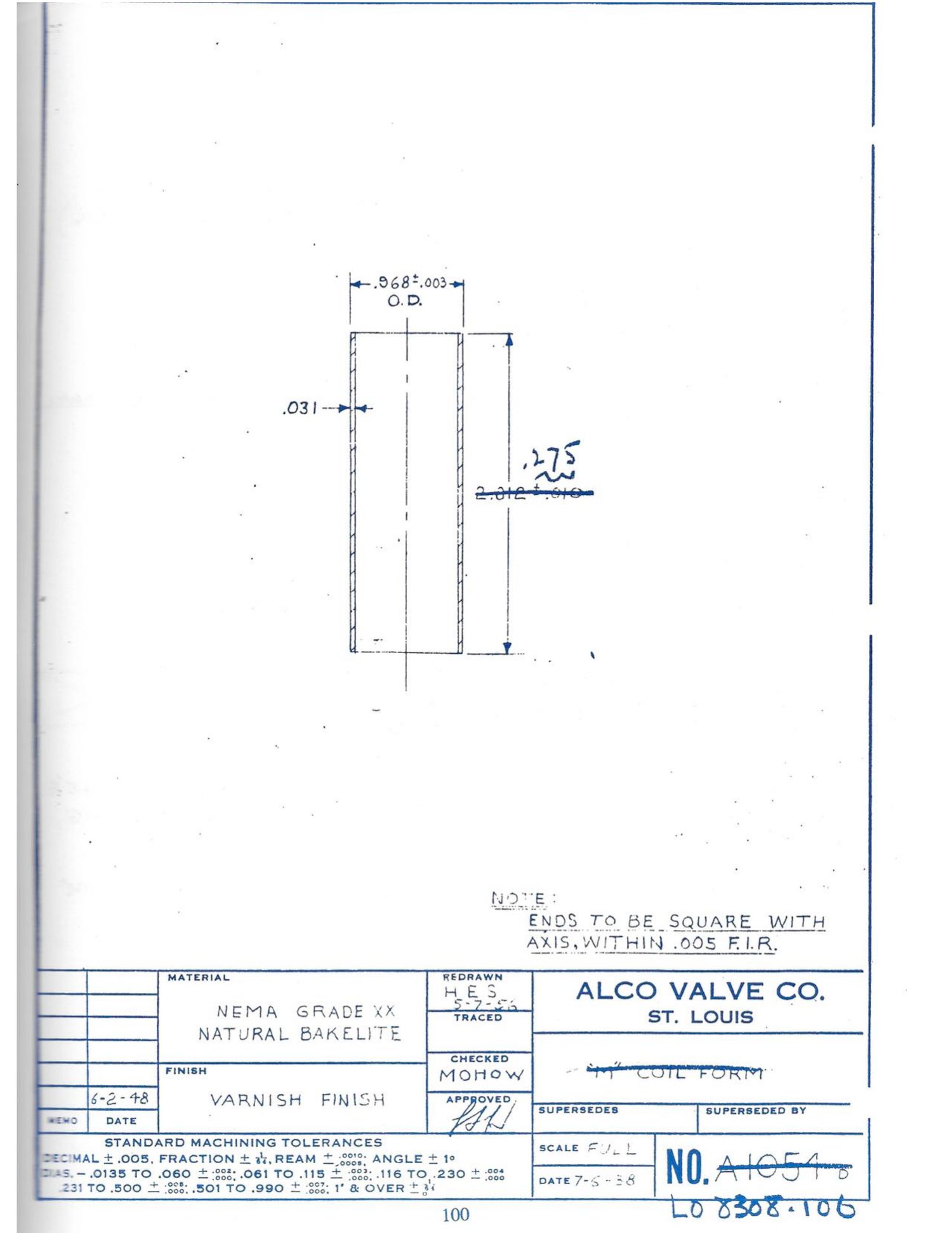
- Tube, section: ".968 ±.003 O.D."; wall ".031"; length: printed "2.012 ±.010" crossed out → handwritten ".275"
- "NOTE: ENDS TO BE SQUARE WITH AXIS, WITHIN .005 F.I.R."
14. LO 8308-107 — Coil Assembly, small (j101 / PDF 104)
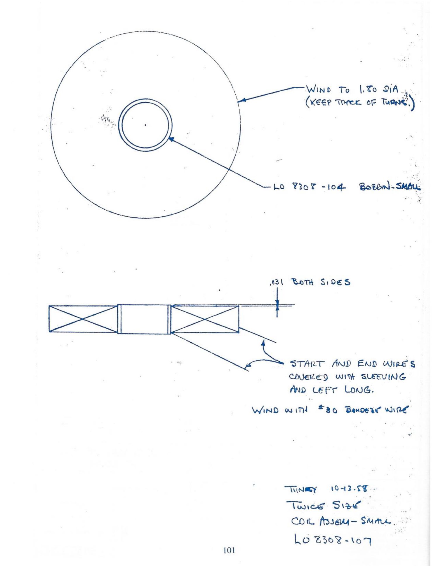
Caption block: "TILNEY 10-13-58 / TWICE SIZE / COIL ASSEM – SMALL / LO 8308-107"
The sheet has two views: a wound-coil face view (annulus) and a side section (winding cross-hatched on both sides of the bobbin):
- Bobbin called out: "LO 8308-104 BOBBIN – SMALL"
- "WIND TO 1.80 DIA (KEEP TRACK OF TURNS.)"
- "WIND WITH #30 BONDEZE WIRE" [Bondeze = bondable magnet wire. The reading of the brand is fair]
- ".031 BOTH SIDES" (winding kept .031 clear of/inside bobbin ends — leader points to bobbin end faces)
- "START AND END WIRES COVERED WITH SLEEVING AND LEFT LONG."
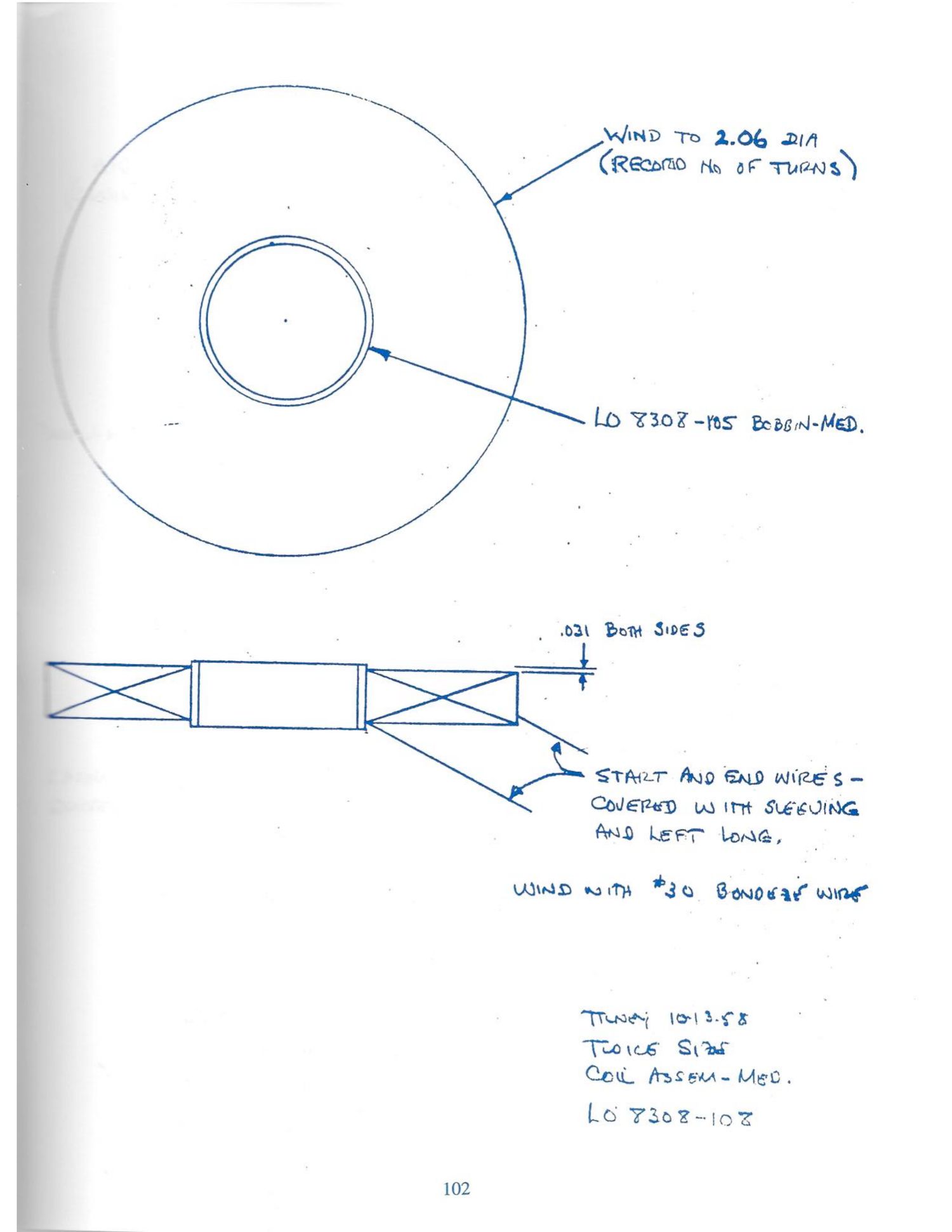
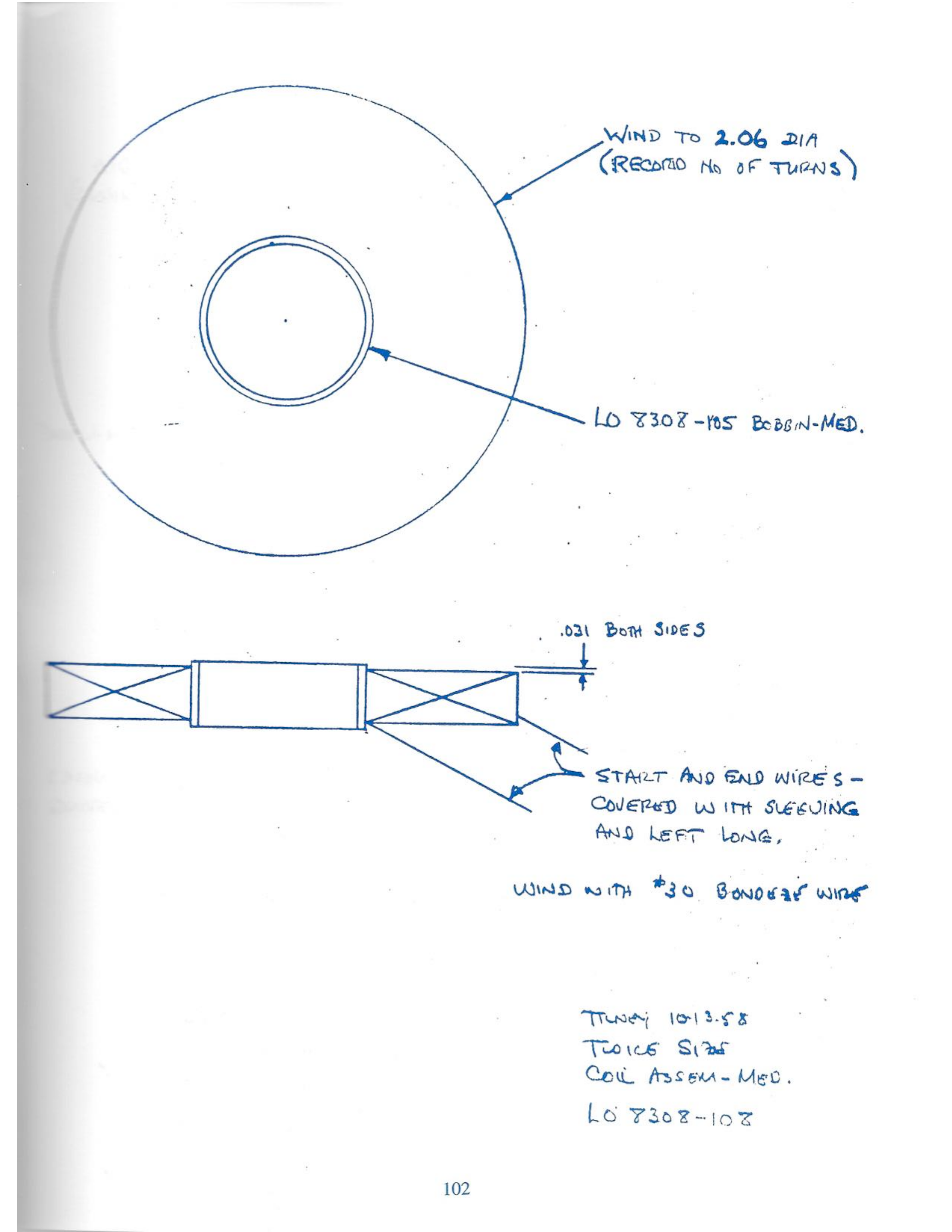
15. LO 8308-108 — Coil Assembly, medium (j102 / PDF 105)
Caption block: "TILNEY 10-13-58 / TWICE SIZE / COIL ASSEM – MED. / LO 8308-108"
The sheet uses the same two-view format:
- "LO 8308-105 BOBBIN – MED."
- "WIND TO 2.06 DIA (RECORD NO OF TURNS)"
- ".031 BOTH SIDES"
- "START AND END WIRES – COVERED WITH SLEEVING AND LEFT LONG."
- "WIND WITH #30 BONDEZE WIRE"
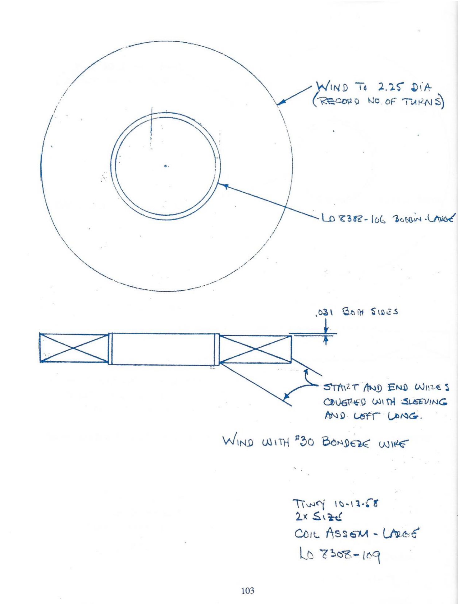
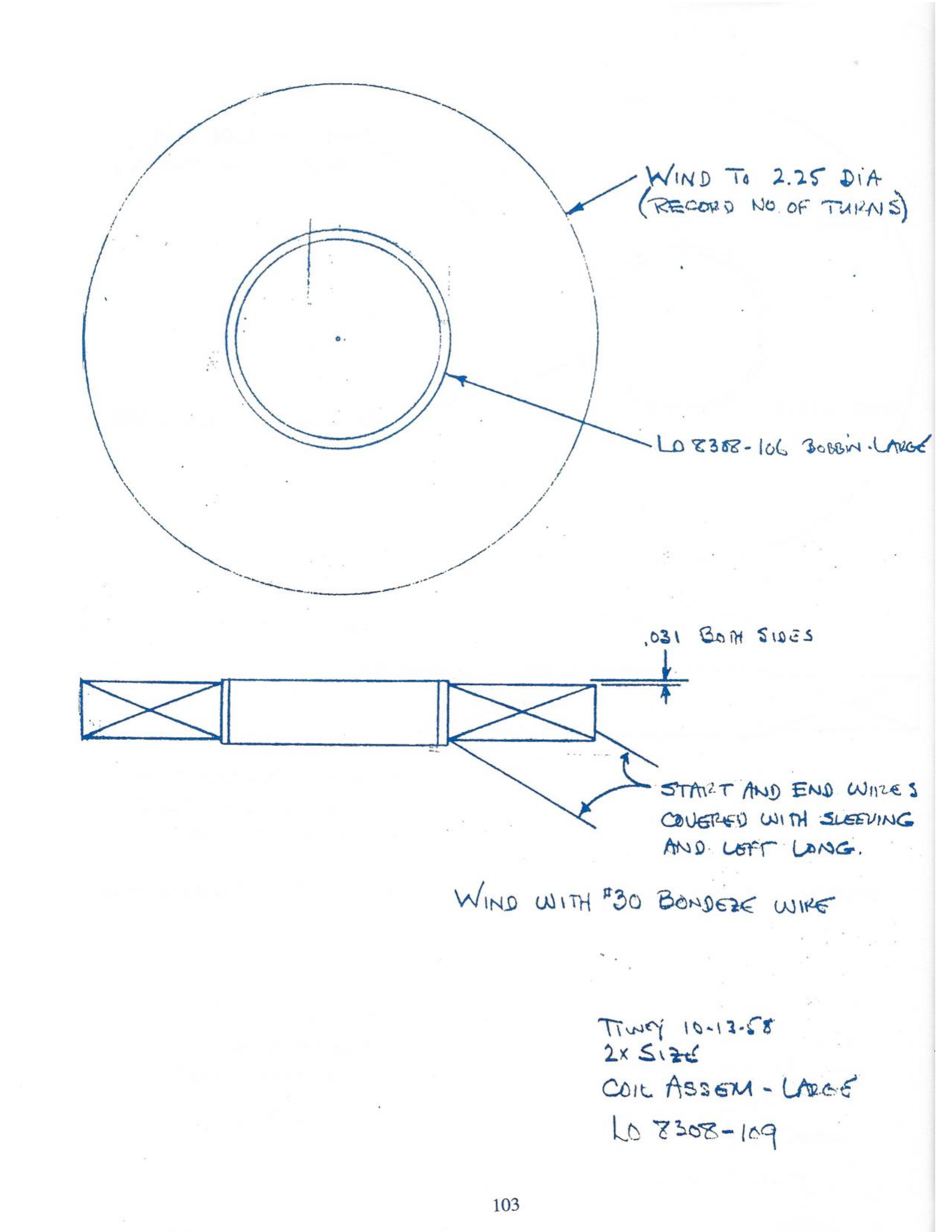
16. LO 8308-109 — Coil Assembly, large (j103 / PDF 106)
Caption block: "TILNEY 10-13-58 / 2X SIZE / COIL ASSEM – LARGE / LO 8308-109"
The sheet uses the same two-view format:
- "LO 8308-106 BOBBIN – LARGE"
- "WIND TO 2.25 DIA (RECORD NO. OF TURNS)"
- ".031 BOTH SIDES"
- "START AND END WIRES COVERED WITH SLEEVING AND LEFT LONG."
- "WIND WITH #30 BONDEZE WIRE"
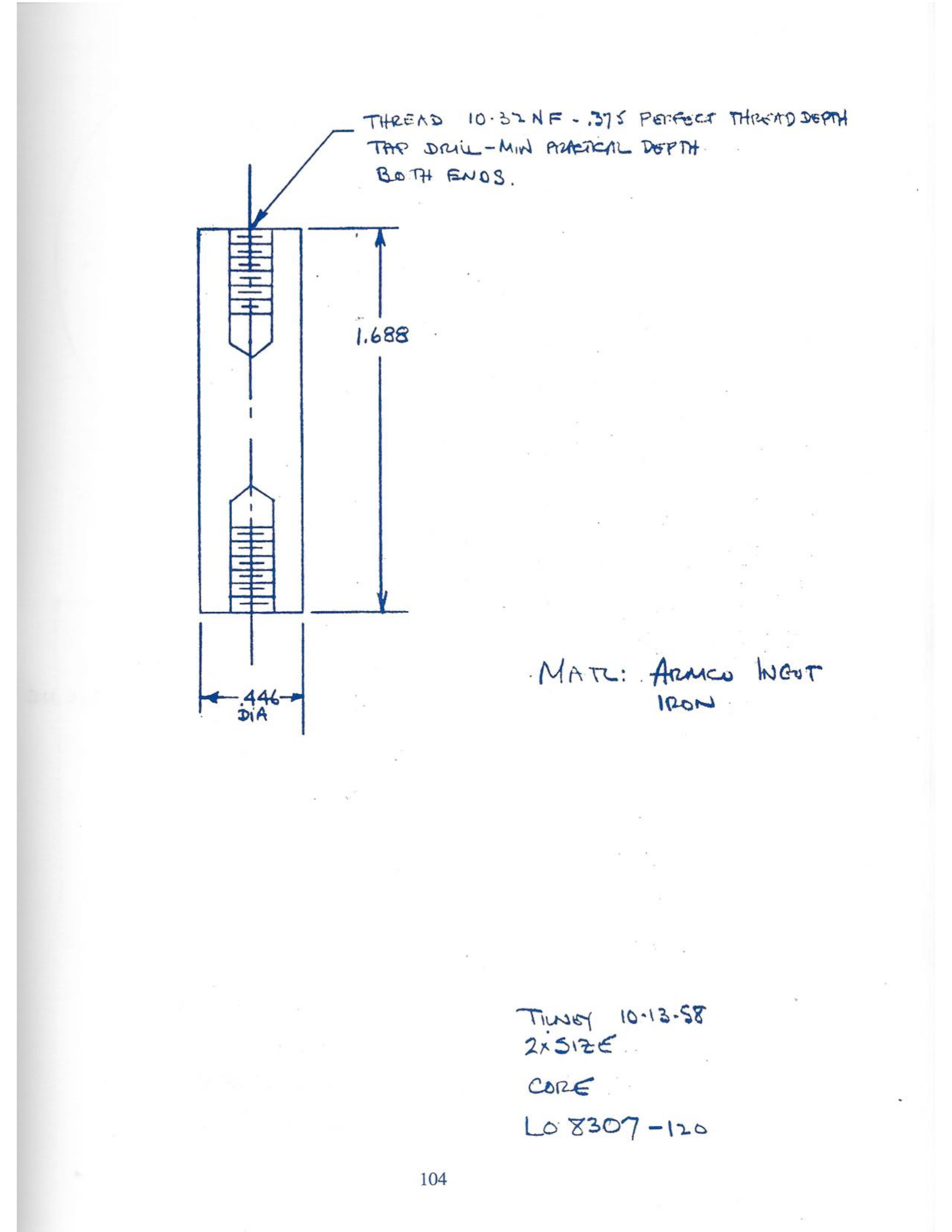
17. LO 8307-120 — Core, conventional unit (j104 / PDF 107)
Caption block: "TILNEY 10-13-58 / 2X SIZE / CORE / LO 8307-120" [the number reads 8307, not 8308 — possibly a sloppy "8". Flagged] "MATL: ARMCO INGOT IRON"
The part is a plain cylindrical core, tapped at both ends:
- ".446 DIA" × "1.688" long
- "THREAD 10-32 NF – .375 PERFECT THREAD DEPTH / TAP DRILL – MIN PRACTICAL DEPTH / BOTH ENDS."
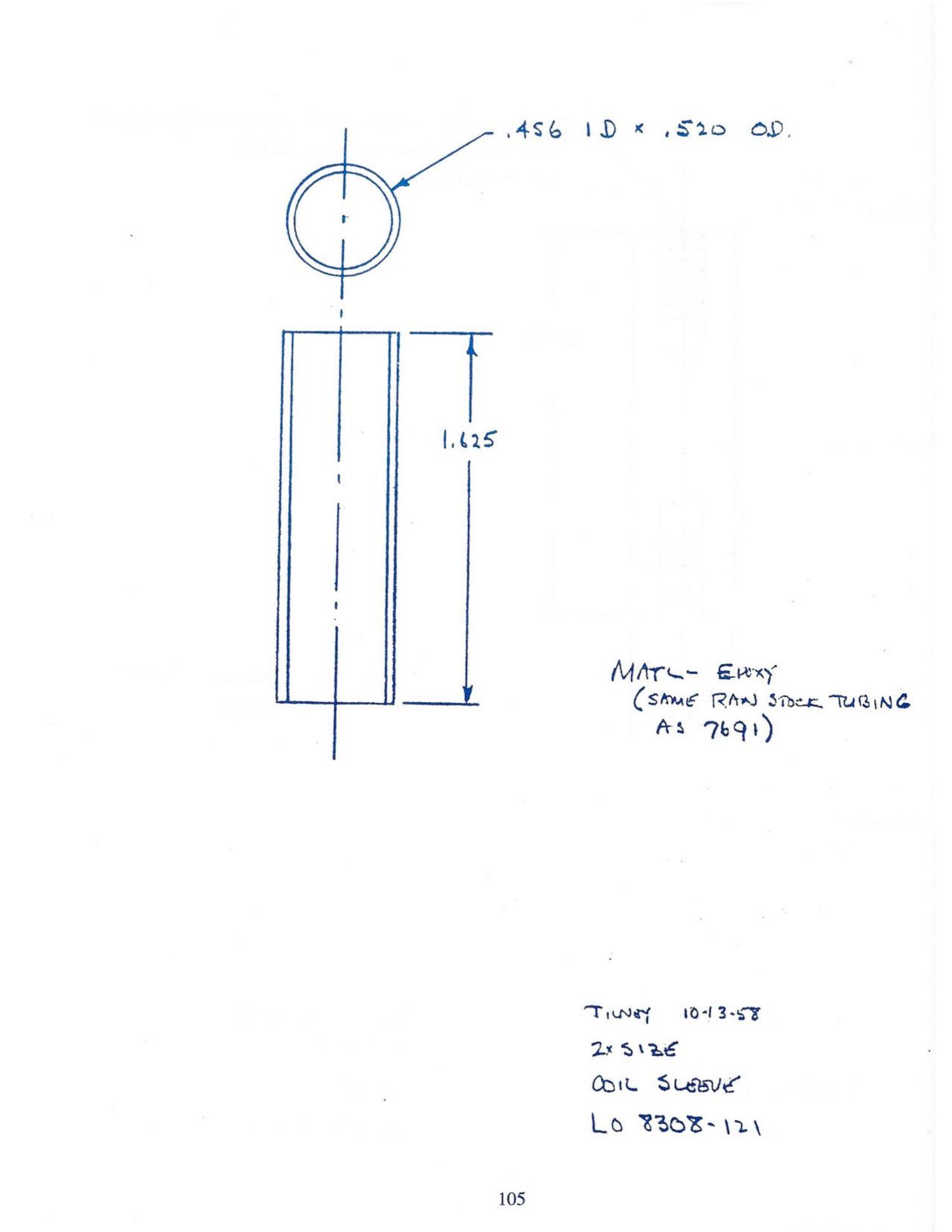
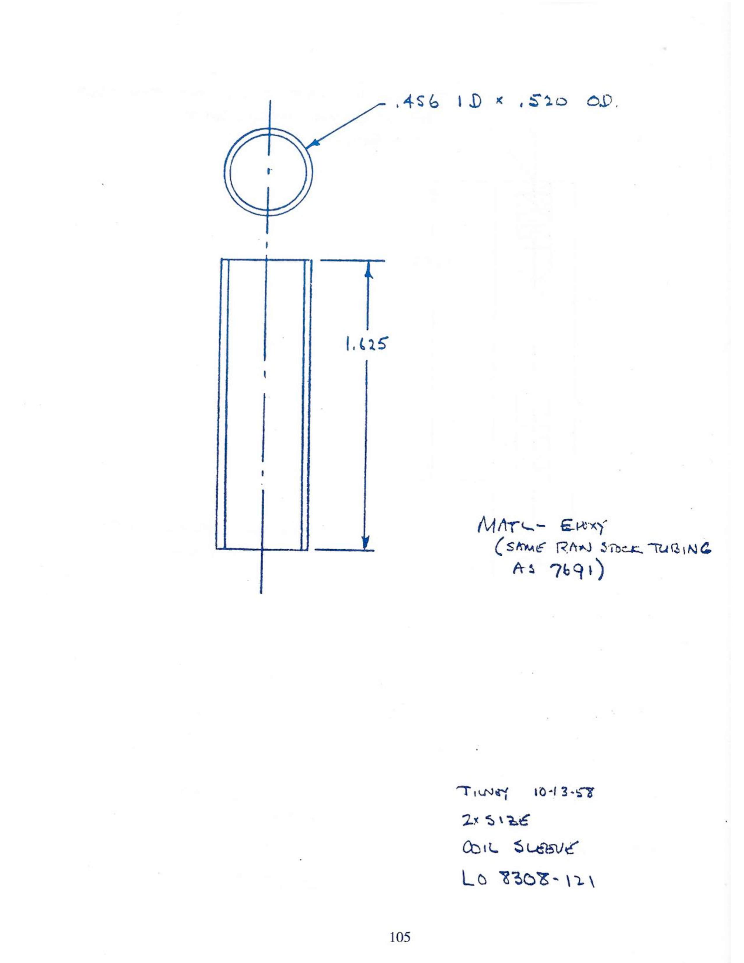
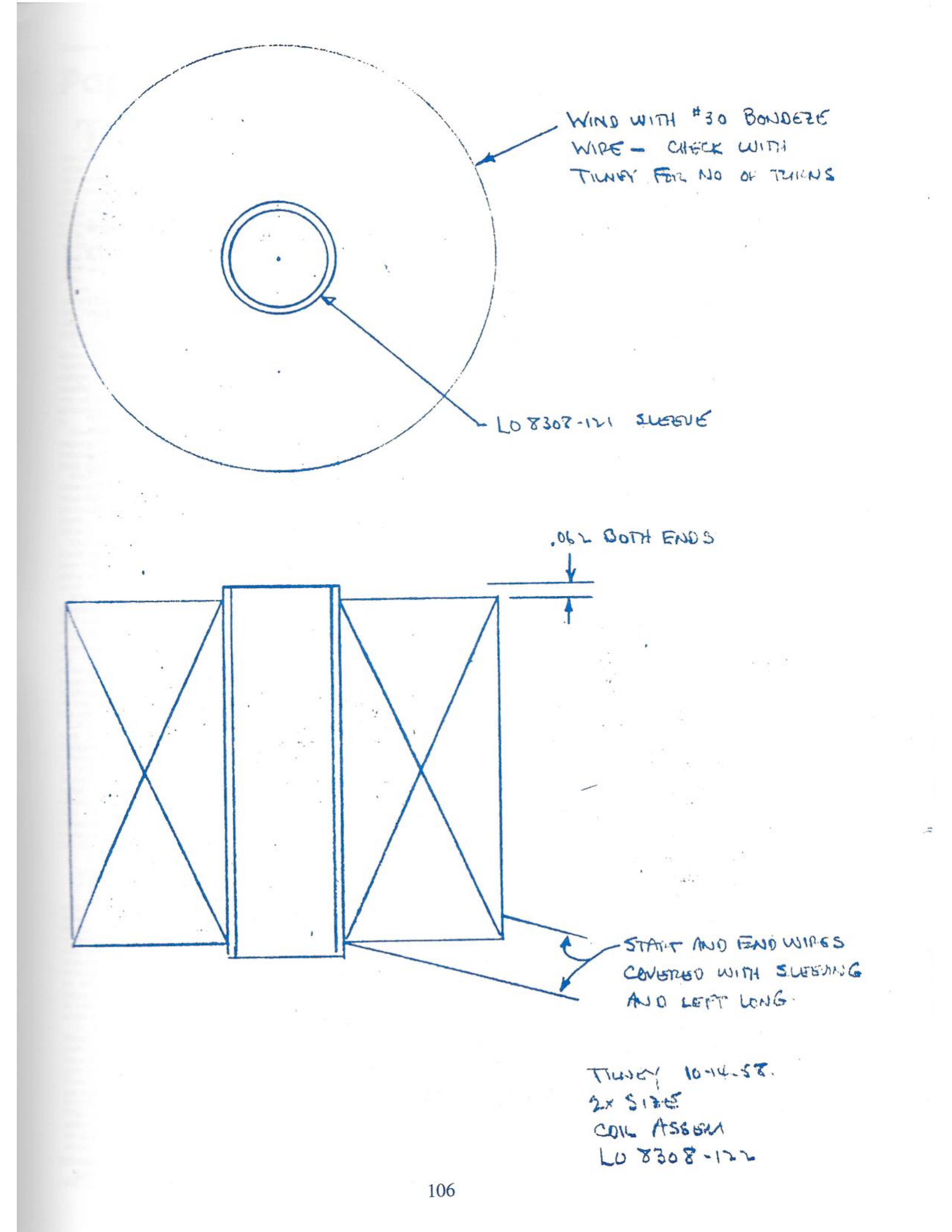
18. LO 8308-121 — Coil Sleeve, conventional unit (j105 / PDF 108)
Caption block: "TILNEY 10-13-58 / 2X SIZE / COIL SLEEVE / LO 8308-121"
The part is a thin tube, shown in an end view and a side section:
- ".456 ID × .520 OD"
- Length "1.625"
- "MATL – EPOXY (SAME RAW STOCK TUBING AS 7691)" [7691 = another Alco part/stock number]
19. LO 8308-122 — Coil Assembly, conventional unit (j106 / PDF 109)
Caption block: "TILNEY 10-14-58 / 2X SIZE / COIL ASSEM / LO 8308-122"
The sheet has two views: a face view (large annulus on a small sleeve) and a side section (two cross-hatched winding blocks on the sleeve, center land bare):
- "WIND WITH #30 BONDEZE WIRE – CHECK WITH TILNEY FOR NO OF TURNS"
- "LO 8308-121 SLEEVE" (center)
- ".062 BOTH ENDS" (sleeve protrusion beyond winding at each end) [".062" reading fair]
- "START AND END WIRES COVERED WITH SLEEVING AND LEFT LONG."
Prose description of the coil geometry (for CAD reconstruction)
Russell ("step diameter") test unit — LO 8308-11 assembly. The unit is a body-of-revolution assembly that approximates a sphere of ≈2.25 in max diameter. The magnetic core is two identical Armco-ingot-iron "core halves" (LO 8308-101). Each half is a three-step cylinder: diameters .891 → .708 → .446 step down toward the outer (pole) end, with intermediate diameter .521 and a .765±.001 spigot at the inner (equatorial) end. A steel core sleeve (LO 8308-102, .688 ID nominal / .767±.001 press-fit bore, .312 long) joins the two halves nose-to-nose at the equator, pressed over the .765 spigots. This gives a continuous solid core with NO through hole (per Dube's Oct 2 revision, which Russell accepted Oct 5). Each pole end is tapped 10-32 NF and receives an Armco iron hex "button" (LO 8308-103, 5/8 hex head .281 thick, .375 thread). The button serves as the pull-test attachment/pole piece.
Six annular windings in three sizes (two of each) stack around this core. They are mirror-symmetric about the equator, with the largest pair at the equator and the smallest at the poles. This is the stepped approximation of Russell's "tornado"/sphere profile:
- Small pair: epoxy bobbin LO 8308-104 (.456 ID / .520 OD / .275 long) wound to 1.80 OD
- Medium pair: bakelite bobbin LO 8308-105 (.781 OD tube, .031 wall, .275 long) wound to 2.06 OD
- Large pair: bakelite bobbin LO 8308-106 (.968 OD tube, .031 wall, .275 long) wound to 2.25 OD
All six sections are wound with #30 Bondeze (bondable enamel) magnet wire, nominally 500 turns/section (per Dube's Aug 25 letter and the Fig. 2 note). The assembly sheets say "record no. of turns" — the final counts are not stated. Electrical connection (Fig. 2): the three sections of each hemisphere [INFERENCE — grouping into upper/lower three is the natural reading of "2 groups of 3 sections"] are wired in series. The two groups are paralleled across the supply. The measured resistance of the step-coil pair is 126 Ω (Russell-side Fig. 2, j91).
Note: the bobbin bores (.456 small, ~.72 medium [INFERENCE: .781 OD − 2×.031 wall = .719 ID], ~.906 large [.968 − .062]) correspond to the core step diameters .446 / .708 / .891. That is, each winding sits on its own core step with ~.005–.015 radial clearance.
Conventional ("standard") test unit — LO 8308-12 assembly. A straight Armco iron core (LO 8307-120, .446 dia × 1.688 long, both ends tapped 10-32 NF ×.375) sits inside an epoxy sleeve (LO 8308-121, .456 ID / .520 OD × 1.625 long). A single winding (LO 8308-122) of the same #30 Bondeze wire is wound on the sleeve (drawn as two hatched blocks in section — the sleeve ends protrude .062). The wire quantity was to equal the Russell unit's ("check with Tilney for no. of turns" — Dube: "wound with the identical amount of wire of the same size"). The measured resistance of the standard pair is 131 Ω (Fig. 1, j91). The buttons/pole attachments are as for the fixture. In the LO 8308-12 concept sketch, the two core ends inside the bore are chamfered to points that face each other across a small gap.
Pull test (Figs. 3–4, j91–92). Two identical units of a type were mounted coaxially with a controlled "GAP" between the pole faces. The upper unit hung from a fixed anchor. A spring scale measured the breakaway force at 24 VDC. Result (calibrated): standard coils 5.09→1.32 lb over gaps 0→.040 in, step-diameter coils 4.80→1.21 lb. The conventional design out-pulled the Russell design at every gap, consistent with the report's "5 to 10% more pulling power throughout the range."
Ambiguities / flags
- LO 8307-120: prefix digit "7" vs "8" uncertain (all sibling parts are 8308-1xx).
- LO 8308-101: the assignment of .469/.188/.843/.281/.281 to specific steps is interpretive (overlapping freehand leaders). The diameters are secure.
- Fig. 4: the header date "17 NOV '58" and the initials "JSY" are uncertain. The curve values are calibrated re-reads per §5 (±0.05 lb, or ±0.1 lb for the zero-gap pair).
- Fig. 1 (j88): the cursive note reading is uncertain, including the circled reference "(4)"/"(a)".
- LO 8308-104: the superseded drawing number (crossed out) and the memo number are partly illegible. The "RESDEL CORP." reading is fair.
- ".031 BOTH SIDES" on the three coil assemblies: the leader points to the bobbin end regions. Whether it dimensions bobbin-flange wall thickness or winding setback is not certain. (The bobbin tube wall is also .031, which suggests it re-states the tube wall as end-face thickness.)
- j91 "131 Ω"/"126 Ω": the page does not label which figure corresponds to which coil type. The assignment (Fig.1 = round/standard helices, Fig.2 = stepped/Russell) is by the drawn coil shapes.